Skip to content
Parallax Learn

Parallax Learn

  • Welcome
  • Tutorials
        • Tutorial Series head tag

          Tutorial Series
        • Tutorial Series

          The special, classroom-ready series pages are organized collections of tutorials for our most popular hardware and/or languages. The tutorials for each topic are conveniently accessible from a single page, shown in the order it is recommended that they be completed.
        • Robotics Series Head tag

          Robotics Series
        • Robotics Series

          • Artificial Intelligence
          • Cybersecurity: Radio Data tutorialCybersecurity
          • cyber:bot + Python
          • cyber:bot + MakeCode
          • Boe-Bot Tutorial SeriesBoe-Bot
          • Arduino Shield-Bot
          • ActivityBot with C TutorialsActivityBot + C
          • ActivityBot with BlocklyProp Tutorial SeriesActivityBot + BlocklyProp
          • Scribbler 3 Tutorial SeriesScribbler 3
        • Electronics & Programming Series Head tag

          Electronics & Programming Series
          • BS2 Board of Education Tutorial SeriesBS2 Board of Education
          • Propeller C-Language BasicsPropeller C Basics
          • FLiP Try-It Kit C Tutorial SeriesFLiP Try-It Kit + C
          • FLiP Try-It Kit BlocklyProp TutorialsFLiP Try-It Kit + BlocklyProp
          • Badge WX Tutorial SeriesBadge WX
          • Propeller BlocklyProp Basics and ProjectsPropeller BlocklyProp Basics
          • View All Tutorial Series »
        • Browse Tutorials
        • Browse Tutorials

          Individual tutorials sorted by robot or kit, and language.
        • By Robot or Kit
          • ActivityBot
          • SumoBot WX
          • Boe-Bot
          • Shield-Bot
          • cyber:bot
          • Badge WX
          • ELEV-8
          • ARLO
        • By Language
        • By Language

          • Propeller C
          • Arduino
          • BlocklyProp
          • PBASIC
          • Python
          • MakeCode
          • View All Tutorials »
  • Educators
  • Reference
  • Downloads
  • Home
  • All Courses

Arlo Robot Assembly Guide

Curriculum

  • 1 Section
  • 47 Lessons
  • Lifetime
Expand all sectionsCollapse all sections
  • Arlo Robot Assembly Guide
    47
    • 1.1
      Section 0 – Getting Ready to Build Arlo
    • 1.2
      Section 1 – Motor Mount and Wheel Kit Assembly
    • 1.3
      Step 1 – Axle Assemblies
    • 1.4
      Step 2 – Motor to Bearing Block Assembly
    • 1.5
      Step 3 – Drive Axle Pin
    • 1.6
      Step 4 – Bearing Block and Axle
    • 1.7
      Step 5 – Soldering the Encoder Connectors
    • 1.8
      Step 6 – Encoder Cables
    • 1.9
      Step 7 – Encoder Assemblies
    • 1.10
      Step 8 – Drive Wheels
    • 1.11
      Step 9 – Wheel Assemblies to Drive Shaft
    • 1.12
      Section 2 – Caster Wheel Kits
    • 1.13
      Step 10 – Swivel Rod and Mounting Plate
    • 1.14
      Step 11 – Swivel Block
    • 1.15
      Step 12 – Flange Bearings
    • 1.16
      Step 13 – Shaft Collar and Swivel Post
    • 1.17
      Section 3 – Mounting Wheel Assemblies
    • 1.18
      Step 14 – Lay Out the Parts
    • 1.19
      Step 15 – Motor Mounts to Arlo Base
    • 1.20
      Step 16 – Casters to Arlo Base
    • 1.21
      Step 17 – Screws and Standoffs
    • 1.22
      Section 4 – Arlo Power Distribution Board
    • 1.23
      Step 18 – Low-Profile Components
    • 1.24
      Step 19 – Diodes
    • 1.25
      Step 20 – Fuse Holders
    • 1.26
      Step 21 – Terminal Blocks
    • 1.27
      Step 22 – Switch Terminals
    • 1.28
      Step 23 – Charging Power Jack
    • 1.29
      Step 24 – Voltage Regulators and Heat Sinks
    • 1.30
      Step 25 – Polarized Capacitors
    • 1.31
      Step 26 – Switch Plate
    • 1.32
      Step 27 – Switch Plate Assembly to PDB
    • 1.33
      Section 5 – Batteries and Battery Tray
    • 1.34
      Step 28 – Prepare Battery and Tray
    • 1.35
      Step 29 – Batteries and Tray
    • 1.36
      Section 6 – Assembling and Mounting the Ping))) Sensors
    • 1.37
      Step 30 – Light Pipe and Protector Stands
    • 1.38
      Step 31 – Attach Ping)))s to Stands
    • 1.39
      Section 7 – Control Components and DHB-10 Connections
    • 1.40
      Step 32 – Arlo Power Distribution Board
    • 1.41
      Step 33 – DHB-10 and Control Board
    • 1.42
      Section 8 – Arlo Top Deck
    • 1.43
      Step 34 – Wiring the DHB-10 Power Connections
    • 1.44
      Step 35 – Wire PDB to Battery
    • 1.45
      Step 36 – Prep the Barrel Jack Connection
    • 1.46
      Step 37 – Connecting Power & Encoders
    • 1.47
      Step 38 – Mount Top Deck

Step 29 – Batteries and Tray

Standard Double-Battery Configuration

For the Single-Battery Configuration diagram, click here or scroll to the end of this step.

Before you install anything: the (4) counter-sunk side of the mounting holes (that fasten the tray to the bottom of the motor mount blocks) should be facing down (opposite side of where the batteries and standoffs are) so that the flat head screws will seat properly when the battery assembly is connected to the motor mount and wheel assemblies.

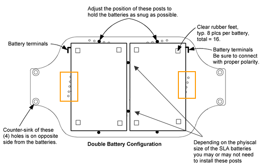
  • Use the above diagram to install posts on the battery tray. Note the locations of the battery terminals as oriented on the tray.

Note: The physical size of the batteries (that are included in the Arlo Complete Robot System) may vary slightly due to battery manufacturing tolerances.  Therefore, it may not be necessary or feasible to install the middle retention posts. If you choose not to install the central posts, there are other optional holes to install retention posts on the outsides of the battery tray (close to the terminals) which have been outlined in the above image with an orange box. Use the best configuration for your battery size and setup.

If you’re using the standard 12 V, 7.5 Ah sealed lead acid (SLA) batteries (that come with the Arlo Complete Robot System), the (included) 5/8” F/F standoffs and #4-40 x ½” long pan-head screws will hold them securely as shown. The staggered hole patterns accommodate slight dimensional variances between different brands of batteries.  Use the (staggered) holes that provides for the tightest retention of each of the batteries.  

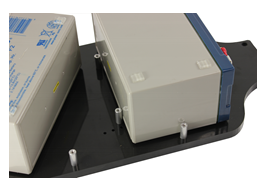
  • Place the batteries on the tray with the retention posts to make sure there’s a snug fit, (shown with middle posts installed):

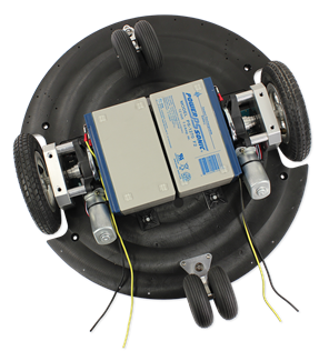
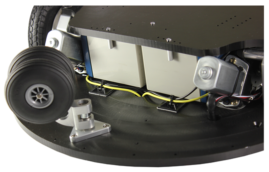
  • Flip your Arlo base platform over and lay the batteries in between the motor mount assemblies, as shown here:

  • Now place the battery tray over the batteries (with the standoffs separating them). Secure the tray to the motor mount blocks with (4) ¼”-20 x ¾”, flat socket-head screws – the same type of screw that was used to attach the motor assemblies to the Arlo base.  Feed the battery wires through the hole as shown and be sure that the wire ends are still covered with tape to prevent any short circuits.

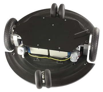
  • Peel and stick a couple of zip-tie anchors to the bottom of the platform as shown below and secure the power wiring with a couple of zip ties from the Hardware Pack for Arlo.

This completes the installation of the batteries and the battery tray. 


Single-Battery Configuration

If you wish to mount a single 12 battery to the Arlo Platform instead, use the following Single-Battery Configuration shown here:

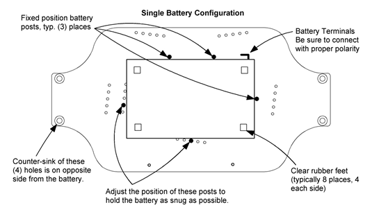
Complete battery tray installation by following the tray mounting-procedures as outlined in the double-battery configuration instructions, above.


Printer-friendly version
Step 28 – Prepare Battery and Tray
Prev
Section 6 – Assembling and Mounting the Ping))) Sensors
Next

DISCUSSION FORUMS | PARALLAX INC. STORE

About | Terms of Use | Feedback: learn@parallax.com | Copyright©Parallax Inc. 2024

© 2026 Parallax Learn • Built with GeneratePress