Build and Test the Alarm
Schematics and Building the Circuits
The figures below provide the schematic and wiring diagram for the door alarm project.
Figure 1 – Door Alarm Schematic
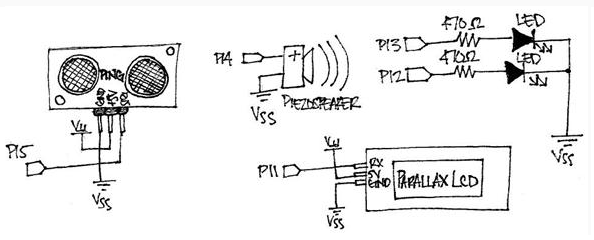
Figure 2 – Door Alarm Wiring Diagram
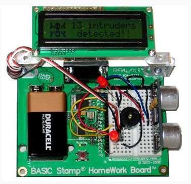
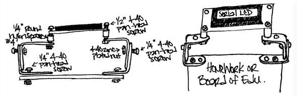
If you take a look at the wiring diagram (Figure 2) above, you may notice that the Parallax Serial LCD is mounted to the board using 90-degree universal mounting brackets. These are are not required for the project; however, if you would like to use them to mount your Serial LCD, please use the optional mounting bracket parts and following assembly diagram:
Figure 3 – LCD Mounting Assembly
Testing the Circuit
Before continuing, it’s always a good idea to check the wiring for any errors. This will help save valuable troubleshooting time as you will already know that each component is connected correctly.
- Run TestAlarmCircuit.bs2 and verify that the following occurs:
- The piezospeaker emits a tone
- The LEDs turn on
- The echo time of the Ping))) sensor is displayed on the Serial LCD
' TestAlarmCircuit.bs2
' Checks that each aspect of the alarm circuit is working.

' {$STAMP BS2}
' {$PBASIC 2.5}

time      VAR   Word
counter   VAR   Byte

SEROUT 11, 84, [22, 12]          ' Initialize the LCD
PAUSE 5

FREQOUT 14, 500, 2000            ' Play a tone

DO
  PULSOUT 15, 5                  ' Get echo times
  PULSIN  15, 1, time

  HIGH 13                        ' Turn LEDs on
  HIGH 12

  ' Display echo times on LCD
  SEROUT 11, 84, [128, "time = ", DEC5 time]

  PAUSE 200
LOOP
Before moving on, test the circuit in the area you want to be monitored by the alarm device and make a note of the echo time of the Ping))) sensor when nothing is in its way. Then, when you program the alarm later, you can tell it to activate if the echo time is less than the unobstructed distance of the area you are monitoring.