Get and Display Coordinates with a Program
In the last lessons you trained the HUSKYLENS and saved your training to a microSD card. Now you’ll read where the camera sees your trained target and plot its position on the micro:bit’s 5×5 LED display (X,Y). This is the first step toward making the robot respond to what it sees.
-
Open the MakeCode editor.
-
Start with your previous project (e.g., Learn Colors or Save Colors).
-
If you need to reopen it, click Import on the MakeCode home page and choose your saved file.
-
-
Use the Name field next to Download to name this project: Show Object XY.
-
Update your program so it matches the script below.
-
Click the Save (floppy disk) icon to keep a copy.
-
Press Download to load it onto your micro:bit.
Test the Script
This test builds directly on your earlier Learn Colors work.
Power-up the cyber:bot
-
5 fresh AA batteries (alkaline or recharged NiMH).
-
Battery barrel jack connected.
-
3-position switch set to 1 (center).
Use your trained color
-
If needed, load training from microSD (Logo + B) using your previous save/load script.
-
Press A/B to select the currentId you trained earlier.
Watch the coordinates dot
-
Point the HUSKYLENS at the trained color.
-
You should see a single LED dot plotted on the micro:bit display.
-
Move the target left/right/up/down — the dot should move in the opposite-mapped directions (because we inverted the map to match a “screen-like” view).
-
If nothing is detected, the screen will clear. Re-center the color and check you selected the correct ID.
Try this (optional)
-
Switch to non-inverted mapping (commented lines in the script) and observe the difference in dot motion.
-
Train a second color as ID 2, press A to switch to ID 2, and verify the dot only appears for that color.
How it Works
This script works like a simple feedback loop, but instead of moving the robot, it gives you a visual display of the object’s position. Each cycle, the HUSKYLENS reports the coordinates of the object’s center (x, y) on its 320×240 camera screen. The program scales those values down to fit the micro:bit’s 5×5 LED display.
The result is that one LED lights up at the location that corresponds to the object’s position in the HUSKYLENS view. If the object moves left, the dot shifts left. If it moves up, the dot shifts up. When nothing is detected, the display clears.
This gives you a direct way to “see what the camera sees” in a simplified form, turning continuous camera data into a quick visual guide that updates in real time.
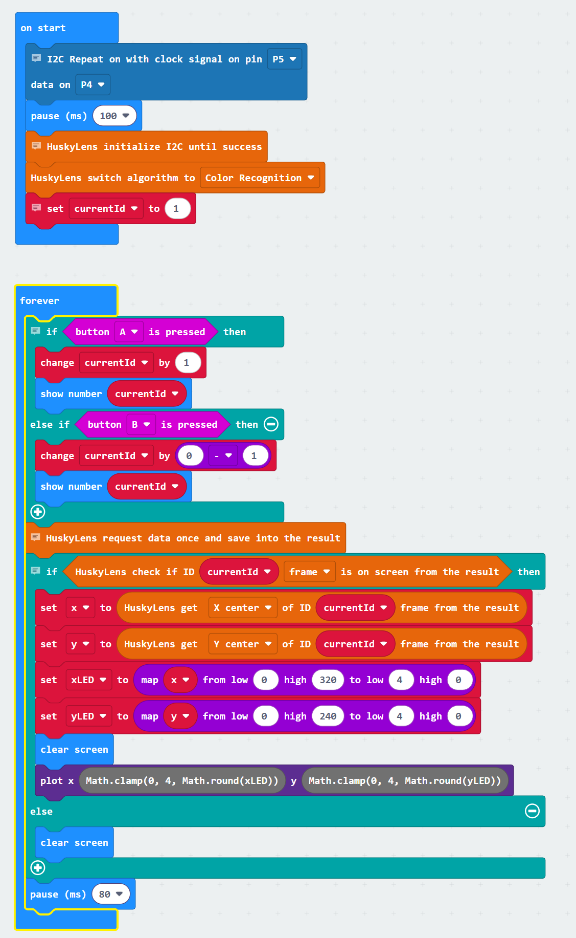
On start setup
-
cyber:bot → I2C Repeat on (clock signal on pin P5 data on P4) — shares the I²C bus with the HUSKYLENS.
-
Basic → pause (ms) (100) — gives the hardware time to settle.
-
HUSKYLENS → HuskyLens initialize I2C until success — starts communication.
-
HUSKYLENS → HuskyLens switch algorithm to (color recognition) — sets the mode for this lesson.
-
Variables → set (currentId) to (1) — starts with ID 1.
Inside the forever loop
-
if <button A is pressed>
→ Variables → change (currentId) by (1) to move to the next ID.
→ Basic → show number (currentId) to display it. -
else if <button B is pressed>
→ Variables → change (currentId) by (–1) to move to the previous ID.
→ Basic → show number (currentId) to display it. -
(after button checks) HUSKYLENS → HuskyLens request data once — updates detections from the camera.
-
if <HUSKYLENS ID (currentId) appears as (block)>
→ HUSKYLENS → read (xCenter) of ID (currentId) intox.
→ HUSKYLENS → read (yCenter) of ID (currentId) intoy.
→ Math → map and Math → clamp to convert camera coordinates (320×240) to LED grid (5×5).
→ Basic → clear screen then LED → plot (xLED, yLED) to show the dot. -
else
→ Basic → clear screen if nothing is detected for this ID. -
Basic → pause (ms) (80) — small delay so the dot doesn’t flicker.