In the tutorial Navigate with Visible Light, you built a circuit and program that allowed an ActivityBot to seek out a bright light. What if you need the robot to seek out a target that you don't want to be visible to people? This tutorial will show you how to use the IR sensors from the Navigate with IR Headlights activitiy, along with an IR LED on another Activity Board, to build both a beacon and an ActivityBot that will seek out the beacon.
The most significant differences between the phototransistors used in the Navigate with Visible Light tutorial and the IR receivers used in the Navigate with Infrared Headlights tutorial are that:
- The phototransistors are analog sensors.
- They can output a range of possible values representing how much light they detect.
- The IR receivers are digital sensors.
- They can only detect if there is — or is not — a modulated IR light present.
The key to making this application work is to get the IR detectors to provide an analog-like output. Unfortunately, there isn’t a good way to do that directly. Instead, what we will do is make the beacon (IR transmitter) behave in an analog manner by varying its brightness. If we check the IR detectors over a period, the more times one of the IR detectors “sees” the beacon, the more directly lined up it is.
Before you Start
- This is a bonus tutorial to follow BlocklyProp Robotics with the ActivityBot 360°. Complete it first!
- Gather the hardware from the lists below. If you have two ActivityBot or ActivityBot 360° Robot kits (#32600), you have all the parts needed!
Building the IR Beacon
What's Needed
- (1) IR LED with its plastic shroud installed.
- You can replace the shroud with a short length of a plastic drinking straw covered in electrical tape.
- (1) 220Ω resistor (red-red-brown)
- (1) jumper wire
- (1) Activity Board or Activity Board WX
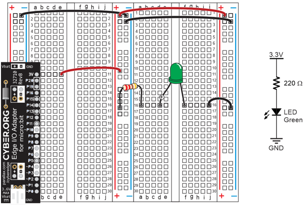
- Build the circuit shown here:
- Start a new BlocklyProp project and build the program shown below:
- Load the code to the Activity Board EEPROM.
We'll test the beacon in a little bit.
Building the IR Seeking ActivityBot
What's Needed
- (2) IR receivers (#350-00039)
- (2) 220Ω resistors (red-red-brown)
- jumper wires
- Built, calibrated and tested ActivityBot or ActivityBot 360°
- Build the circuit below:
Testing the IR Beacon and IR Seeking ActivityBot
- Start a new BlocklyProp project and build the following program:
- Load the code to the ActivityBot.
- Point the IR receivers on the ActivityBot toward the IR Beacon.
- Observe the values shown in the Terminal display.
- Turn your ActivityBot side-to-side, moving it closer and farther away from the IR Beacon to see how the values change.
Programming the ActivityBot to drive to the IR Beacon
- Using the last program you built (above) make a copy into a new project.
- Keep the IR read function, but delete everything else.
- Build the program as shown below (remembering to keep the IR read function from the last program).
- Make sure the power switch on your ActivityBot is in position 1.
- Load the program to EEPROM on your ActivityBot.
- Turn on the IR Beacon you built earlier in this tutorial.
WARNING: When the ActivityBot runs the code above, it will NOT stop when it gets to the IR Beacon! Although the code is designed to help the ActivityBot seek the beacon, there is no good way for it to know when it makes it to the beacon. You will need to add another sensor for that!
- Turn the ActivityBot’s power switch to position 2. You may need to press the reset button.
- Try starting the ActivityBot from different points, angles, and distances. Can you determine the limits of this application?
How the IR Beacon works
Remember that the IR receivers can only report that there is or is not a signal - they cannot report the strength or brightness of the IR signal. Instead, we are varying the strength of the transmitter - the beacon itself. By measuring how many times the beacon is seen over a period while its light is varying allows us to get the IR receivers to behave in a more analog manner.
To generate both the modulated (pulsed) IR signal AND the varying brightness, we will feed two different signals into the LED at the same time. The positive leg of the LED connects to P11, where the code is sending it pulses by turning it on and off 38000 times per second. The negative leg of the LED connects to D/A0, which is changing its voltage output from 0V (full brightness for the LED) to 1.6V (nearly off). Why is 0V bright and 1.6V dim? Because this is where we are connecting the negative leg. The result is that the “Sawtooth”-like output of D/A0 is subtracted from the 3.3V pulses from P11:
Try This - Adjusting the ActivityBot’s Parameters
Three things can be adjusted to alter how the ActivityBot moves toward the beacon.
- The robot’s acceleration
- The “smoothing” variable, which adjusts a low-pass filter
- The “speed” variable, which determines the base speed that the robot drives
A low-pass filter is something that lets slow changes through but blocks fast changes. It does this by adding the newest measurements to the old ones, then averaging them. If you make smoothing smaller, it will give the old values less weight, so more rapid changes are allowed through it. If you make smoothing too large, the ActivityBot may not be able to react quickly enough to turn toward the beacon.
- Try adjusting one of the parameters above. Work to “tune” your ActivityBot to find a good balance between smooth and responsive behavior.
Your Turn
- Add the Ping))) sensor to your ActivityBot to help it stop when it reaches the beacon.