In these activities, you will set up and test your breadboard prototyping system for your micro:bit module. Along the way, you will learn some important circuit building and measuring skills.
You will need:
Complete these tutorials first:
You will be able to:
You will also be ready to move on to the next tutorial (coming soon!)
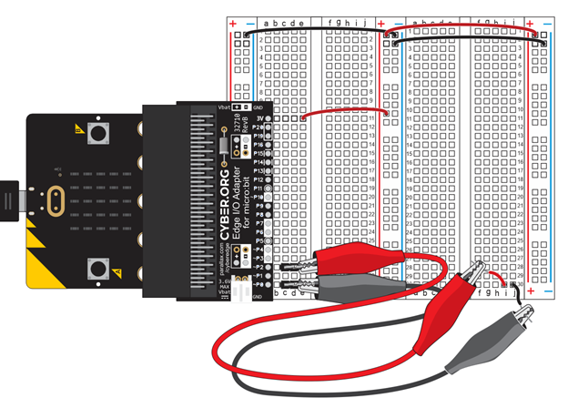
In this activity, you will set up a circuit prototyping system for your micro:bit by connecting it to a breadboard. This system will allow you to quickly and easily connect a variety of additional circuits and extend micro:bit functionality with additional sensors, indicators, motors, and other devices that are not already built into the micro:bit.
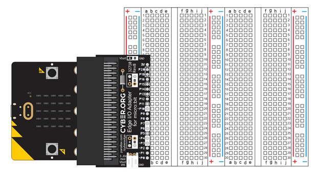
A breadboard is a device that allows you to connect electronic components together on a flat, stable surface. Components are plugged into the grid of holes on the board. Metal clips behind the holes hold the components in place and connect them together.
You might have already built a few simple circuits with alligator clip leads and the micro:bit. That normally works for a few connections, but with more circuits, the project can end up looking like a bowl of spaghetti. This can make keeping track of which parts are connected to each other really challenging. So, the breadboard has become the tool of choice for building circuit prototypes, because it’s way easier to build any number of circuits and still be able to clearly see which parts are connected.
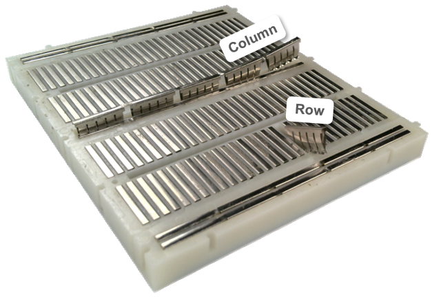
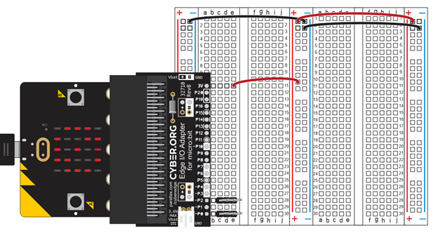
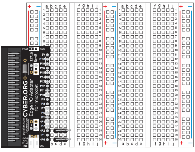
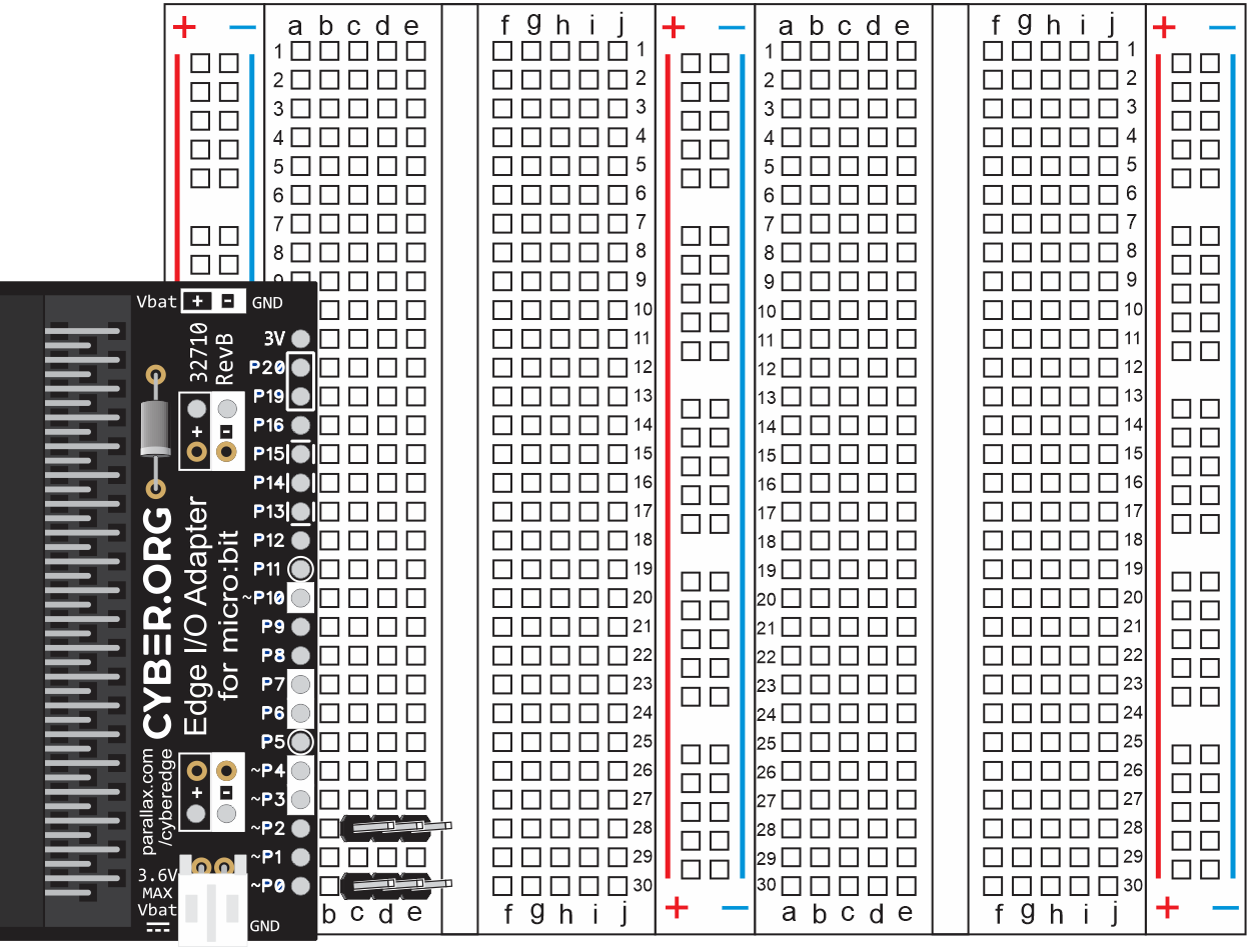
The breadboard you are using in these activities has two terminal strips, each with column labels (a through j) along the top and bottom, and row labels 1 through 30 on each side. Those column and row labels can be used to identify each socket. For example, in the right terminal strip, there’s only one (g, 16) socket. That’s where the g column intersects with the 16th row. The breadboard you’ll be working with also has three bus strips. Each bus strip has two columns, one labeled with a (+) sign and a red stripe, and the other with a (-) sign and a blue stripe.
(View full-size: terminal-strips-row-column-coordinates.mp4)

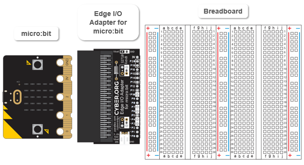
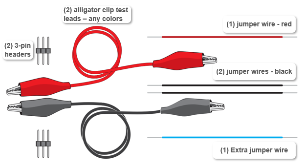
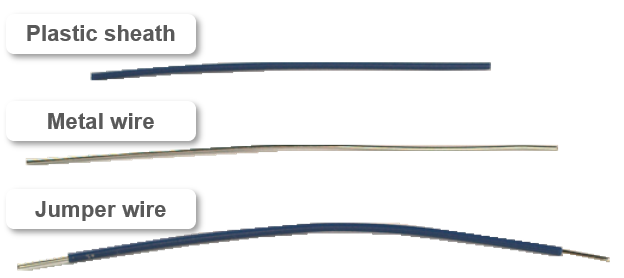
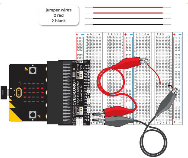
Gather the parts and place them in a row as shown in the picture.
. 
In this activity, you will learn the simple rules of creating electrical connections with a breadboard and test them with the micro:bit. The micro:bit will run a script that beeps and displays a checkmark when it detects an electrical connection. If it does not detect an electrical connection, it will stay silent and display a circle with a slash through it to indicate ‘not connected.’
Here are two simple rules of terminal strips, for the breadboard in your kit:
So, to electrically connect a pair of wires or leads—or up to five at a time— just pick one of the rows of 5 sockets and plug them in.
What if you want to connect a different pair of wires or leads? For those two leads to be electrically connected to each other, but not to the first group, just pick a different row of 5 sockets. Keep in mind that these are rows of 5 sockets, not 10. So, if you plug a wire into (a, 16) and another into (j, 16), they will not be connected. That’s because even though they would be on the same row, they are not on the same row of 5 sockets. Want them connected? Add a wire that connects the two rows.
(View full-size: terminal-strips-for-electrical-connections.mp4)
The row of sockets on the left side of the slot in the center of the terminal strip are electrically insulated from the row of sockets on the right.
So, if your terminal strip has some other number of sockets per row, you can use the slot in the center as your guide for which sockets are connected. Let’s say a terminal strip has 12 sockets per row with 6 sockets to the left of the slot in its center, and 6 more sockets to the right. In that case, for a given row, sockets in columns a through f would be electrically connected. Sockets in columns g through l would also be electrically connected, but they would be insulated from the sockets in columns a through f.
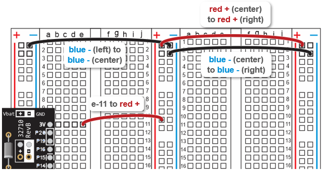
The breadboard in this kit also has three bus strips. Instead of rows of 5, each bus strip has two columns of 25 sockets. All 25 sockets in the column by the blue line are electrically connected, but insulated from all other sockets. The same rule applies for a column of 25 sockets by a red line.
Bus strip columns can also be connected with wires. For example, a jumper wire that is plugged into the (-) column of the center and right bus strips will make it so that a lead plugged into the (-) column of the center bus can be connected to a lead in the (-) column of the right bus.
(View full-size: bus-strips-for-electrical-connections.mp4)
Keep the alligators apart! Adjust the plastic covers on the alligator clips when you connect them to the 3-pin headers, to make sure the two probes are not touching and making electrical contact.
The script you will be working with has a custom module called multimeter added to the project settings. That multimeter module is already part of the .hex file you will download and then open in the micro:bit Python Editor.
Your micro:bit continuity tester will beep (micro:bit V2 only) and display a checkmark when the continuity probes are electrically connected. You can use this to test the various breadboard rows and columns, and even probe rows/columns that have been connected together with jumper wires.
(View full-size: continuity-tester-concept.mp4)
Let’s test all the examples from How to Connect Two Wires.
Modules are files that typically contain Python functions, methods, and properties. After your script imports a module, it can use the functions, methods and properties it contains. For example, the continuity_tester script has this statement: from microbit import * which gives the script access to anything from the microbit module. Without it, the script would not be able to call sleep(50). The script also needs the microbit module for its display.show method and Image.YES property.
# continuity_tester

from microbit import *
from multimeter import *
import music

while True:
    connected = continuity()
    if connected == True:
        display.show(Image.YES)
        #music.pitch(3000, 100)
    else:
        display.show(NC)

    sleep(50)
The continuity_tester script also uses a function named continuity. That function is from a custom module called multimeter. A custom module is different because the micro:bit module’s file system needs the multimeter.py file module before these statements can work properly: from multimeter import * and connected = continuity(). In this activity, the multimeter.py file was already added to continuity_tester.hex.
See Add Modules to your micro:bit for an example of how custom modules are added to a .hex file. In that example, the cyberbot module is used, but the steps of adding the multimeter.py module are similar.You can also download and view the multimeter.py by clicking these items in the python.microbit.org editor:
To view its code, drag it into the python.microbit.org editor. Keep in mind that this code is not a script and so cannot run on its own. It has to be imported into your script, and then your script calls its functions.
Take a closer look at the while True: loop. The multimeter module has a function named continuity(), which returns True if it detects an electrical connection, or False if it does not. In connected = continuity(), the variable connected stores the True/False result continuity returns. When connected stores True , the statements in if connected == True makes the display show a checkmark with display.show(Image.YES). Otherwise, statements in the else block display the not-connected circle with a slash with display.show(NC). Note: NC is property of the multimeter module.
while True:
    connected = continuity()
    if connected == True:
        display.show(Image.YES)
        #music.pitch(3000, 100)
    else:
        display.show(NC)

    sleep(50)
As mentioned earlier, electric current in a circuit is the flow of electrons through that circuit. The flow of electrons in a circuit can do things like make its light element glow, make its motor turn, and so on. Current through a circuit is the result of an electrical pressure called Voltage, which typically has to be connected to a circuit to make the current flow.
In this activity, you will set up supply voltages on the bus strips so that sockets with supply voltages are adjacent to every terminal strip row. This will make it convenient to connect supply voltage to any terminal strip row that might need it. You will make a lot of those kinds of voltage connections to your circuits in upcoming activities.
You will also use the micro:bit running a voltmeter script to check the electrical connections and make sure each one has the correct voltage.
BLANK? Disconnect power! If the display is blank, or only displays the symbol briefly before going blank, disconnect power immediately and check your wiring for errors.
Like the script from First Electrical Connections with a Breadboard, this script is also pre-written as a hex file with the multimeter module added.

Now let’s test the supply rails, first with the Python Editor and then with CYBERscope. In these tests, you will verify that the rails now have 3.3 V.
The wires you added to the breadboard it easy to connect circuits you build on the terminal stips to supply voltages on the bus strips.
The two levels of supply voltage in your prototyping system are 3 V and 0 V.
You can connect a circuit to 3 V by plugging a wire or lead into one of the center and right bus strips’ plus (+) sockets. Those are the ones next to the red lines, and also shaded red in the animation.
The other supply voltage level on the breadboard is 0 V, which is also called ‘ground’ and abbreviated GND. The 0 V level is available from all three bus strips’ minus (-) sockets. Those are the ones next to the blue lines, and also shaded blue in the animation below.
(View full size: bb-voltage-zones.mp4)
Current: Electric current is the flow of electrons through a circuit. Every time a light turns on in your micro:bit module’s display, it’s because current is flowing through it.
Amp: Current is measured in amps, short for amperes, and abbreviated A.
Voltage: The electrical pressure that causes current to flow through your circuit. When the micro:bit’s built-in microcontroller makes a light turn on, it does so by applying voltage to the circuit. That’s the electrical pressure that causes current to flow and the light to turn on.
Volt: Voltage is measured in volts, abbreviated V. Although we’ve been calling it “electrical pressure”, the volt is more correctly a measurement of electric potential. The volt is named after 18th century Italian physicist Alessandro Volta.
Millivolts and milliamps: Abbreviated mV and mA, the millivolt is 1/1000 of a volt, and the milliamp is 1/1000 of an amp. Example: If you measured 3.28 V across the 3V and GND, that could also be expressed as 3280 mA.
Supply rails: When the (+) and (-) columns carry supply voltage, they are sometimes referred to as the positive and negative supply rails.
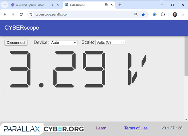
When the system is connected to a USB port, 3 V is actually very close to 3.3 V, typically 3.28 V.
If there’s no USB power and the system is connected to a battery supply, 3 V is determined by the battery voltage. Depending on how new the batteries are, it could range anywhere from 2.6 to 3.2 V.
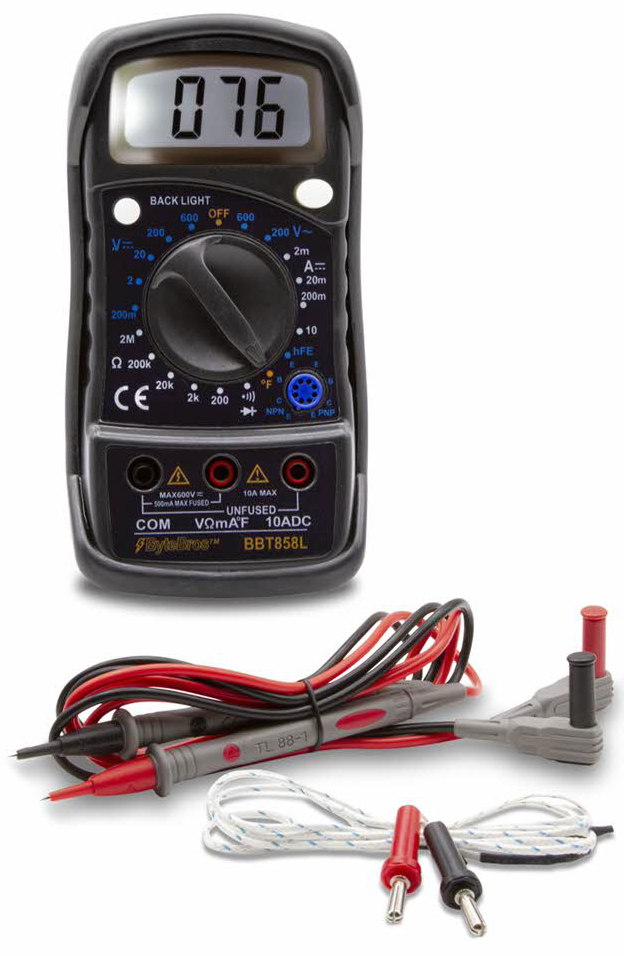
A multimeter is a device that can test for continuity and measure voltage, current, and several other properties that will be introduced as you progress through these lessons. A multimeter’s voltage measurement setting makes it function as a voltmeter. When it is set to measure current, it functions as an ammeter. It’s easier to remember that name if you think of it as an amp meter, with the ‘p’ and space removed. You will be using your micro:bit and a web app to take various multimeter measurements, but a device like the one Digital Multimeter BBT858L is an even better tool for taking those measurements.
Voltage is a measurement of the difference in electric potential between two points. That’s why you get a measurement of about 3.3 V when you connect the P2 alligator clip’s red probe wire to 3V and the P0 alligator clip’s black wire to GND. The difference in electric potential between 3.3 V and 0 V is:
3.3 V – 0 V = 3.3 V.
Let’s try something different.
Repeat the arithmetic example for the 3.3 V result for the three measurements you just took.
Solutions:
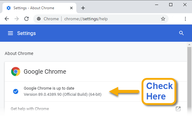
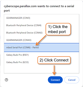
The CYBERscope is a web page app that can work together with your micro:bit to take various multimeter measurements. It can also take other types of measurements, like oscilloscope and logic analyzers, but those will be introduced later. This web app works with Chrome browsers that are Version 89 or newer. The cyberscope.parallax.com page will tell you if your Chrome browser version is compatible.
Up-to-date Chrome Browser
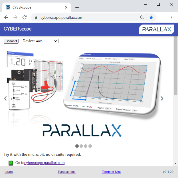
Older version Chrome browser -needs updating!
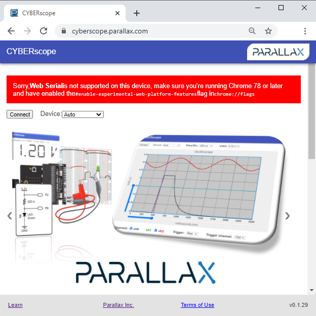
Instructions from here downward are only for browsers that displayed the message with the red banner. If you didn’t see the red banner, just continue to the next page.
 .
.
Now let’s try out the CYBERscope page’s voltmeter display.
Don’t forget to save your work.
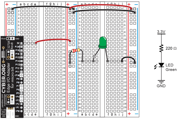
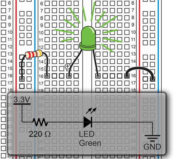
Here is a close-up of the circuit you will build above a diagram called a schematic. A schematic has information about how the parts are electrically connected, but the details of how that circuit is built on a breadboard is up to the person building the circuit. In other words, the circuit you see plugged into the breadboard is just one of many possible “correct” ways to build it.
This activity starts with a simple light circuit. It’s a lot like the lights on your micro:bit, except you can pick the color, red, green, or blue. We’ll start with green.
If this is your first time building circuits on a breadboard, follow along carefully. Along the way, you’ll also get to learn about the parts as well as what happens when electric current flows through the circuit.
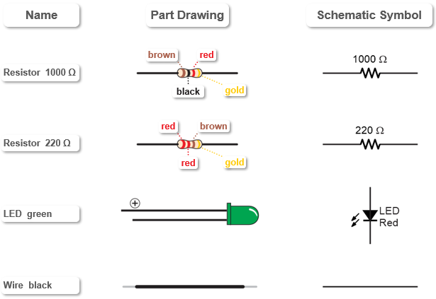
The parts drawing below will help you to identify and gather the electrical components for this activity.
You will also need the completed setup from Set Power for Circuits.
Now, let’s use the components to build the LED circuit on the breadboard.
(View full size:connect-usb-light-on.mp4)
The term LED is an abbreviation for Light Emitting Diode. When current flows through an LED, it emits light. It glows more brightly with more current, and less brightly with less current. That takes care of “light emitting”, now what is a diode? A diode is a one-way valve for electric current. In other words, current can only flow through in one direction. That’s why it’s important to make sure the longer pin is in (d, 16) and the shorter pin is in (f, 16). If the pins are reversed, no current will flow, and the LED will not emit light. The longer (+) pin is called the anode and the shorter one is the cathode.
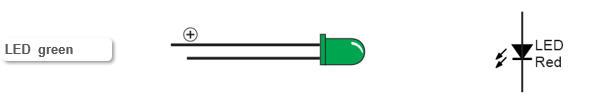
No longer pin? If an LEDs pins get cut to the same length, there’s a flat spot on the round plastic case next to the cathode pin to help identify it.
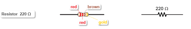
A resistor “resists” the flow of current. Resistance is measured in ohms and abbreviated with the greek letter omega (Ω). Most resistors have color bands that indicate what their resistance values are. More on that later.
The 220 Ω resistor in this activity limits the current through the LED to about 5 mA, which is 5/1000 of an amp. The maximum current for these LEDs is 20 mA. Larger values of resistance will let less current flow, making the LED dimmer. Likewise, smaller resistance values will let more current flow through, making the LED brighter.
Resistors plug in either way. Unlike diodes, you won’t have to worry about what direction to connect a resistor. Resistors resist current the same amount in either direction.
By connecting one end of the LED circuit to 3.3 V and the other end to GND (0 V), the electrical pressure propelling current (electron flow) through the LED circuit is 3.3 V.
One of the most common identification schemes for resistors is the four-band color code. Each of the four color bands on your resistors represents a value.
To read a resistor, position it so that the fourth band, which is going to be gold, silver or blank, is on the right. The left two bands are the first two digits in its resistance value. The third band is the number of zeros to append to the resistance value.
You can use the digits in the Resistor Color Codes chart to figure out what digit each color indicates. The fourth band is the tolerance. That’s a measure of how far the parts actual resistance might be from what the color bands say.
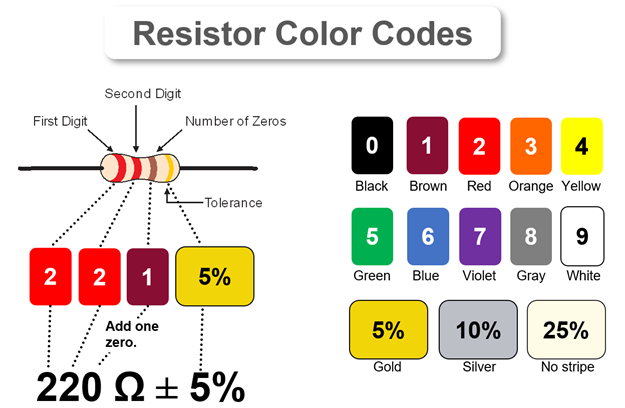
In the example of a resistor with red-red-brown-gold color bands, the first two digits are red, red. Since red is the digit 2, the red-red bands mean 22. The third band is the number of zeros to add to the value. Since the brown band is 1, it means add one zero, for 220 Ω. The gold color band means the resistor has a 5% tolerance. 5% of 220 Ω is 11 Ω, so the resistor’s actual value will be somewhere between 209 and 231 Ω.
Other Color Codes: The rules in this resistor ID table cover the four-band resistors in your kit. There are more digit and tolerance options. For more complete color band ID tables, check the Electronic color code at Wikipedia.
Look at the picture of a battery-powered LED circuit below. A battery contains chemicals with an excess of electrons connected to its (-) terminal and chemicals that are missing electrons connected to its (+) terminal.
With the LED circuit connected, the electrons escape molecules in the chemical where they are already overcrowded, flow from the battery’s (-) terminal through the circuit to its (+) terminal, and then join the chemical with molecules that are lacking electrons. The molecules that lose their extra electrons go from being negatively charged (-) to being neutral (n). Likewise, when the positively charged (+) molecules that are lacking electrons gain an electron, they also become neutral (n).
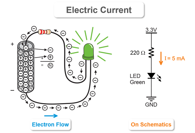
Current is represented quite differently on a schematic. It is typically indicated by an arrow pointing from the higher voltage to the lower voltage. There might be some number of amps (A) or milliamps (mA) next to the arrow. It might even contain an expression like I = 5 mA. The variable I is commonly used as the variable to store current in calculations.
Your circuit used the 220 Ω resistor. Now let’s try the 1000 Ω resistor.
The LED should be noticeably dimmer.
![]()
In this tutorial, you set up a circuit prototyping system.
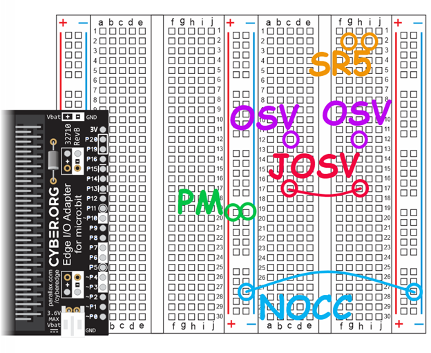
For the following exercises, download and print the attached PDF or a larger version of the image below to circle and label sockets. If possible, test for continuity on your actual board.
Breadboard Setup & Testing Practice and Answers (.pdf)
