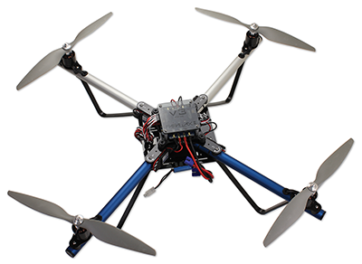
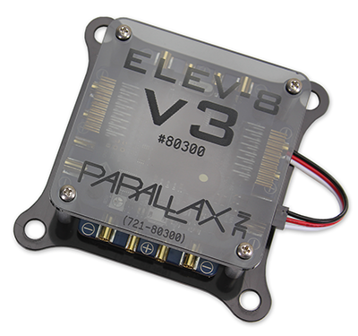
Congratulations and thank you for purchasing a Parallax ELEV-8 v3 Quadcopter, designed and manufactured in California, USA. If you require assistance, please do not hesitate to e-mail or call us.
These instructions are for the Parallax ELEV-8 v3 Quadcopter (#80300) in its standard configuration. (If you have the ELEV-8 v2, go to the v2 Assembly Guide instead.) To work offline or from paper, Click on the “Printer-Friendly Version” link at the bottom-right corner of this page (it may take several minutes to load). Be advised it’s around 100 pages when printed.
If you have an ELEV-8 Quadcopter you must register it with the Federal Aviation Administration’s UAS Registry before flying outdoors.
This guide will take you through assembly and configuration of your ELEV-8 v3 Quadcopter Kit. But first, go through the Preparation list below. Please do not rush through the assembly and testing process! Go slowly and don’t skip anything, to avoid a dysfunctional quadcopter and extensive troubleshooting. It never hurts to double-check your work at each step!
BEFORE beginning assembly of your ELEV-8 v3 Quadcopter, please read the entirety of the UAV Safety, Laws, and Good Citizenship guide. The owner, operator, and pilot of every ELEV-8 v3 are to abide by all laws, regulations, and guidelines, including, but not limited to, those detailed in the aforementioned document. Reading and abiding by the entire UAV Safety, Laws, and Good Citizenship document could help prevent property damage, personal injury, prosecution, and fines.
These items are required for ELEV-8 v3 Quadcopter flight and are NOT included in your basic kit.
We also recommend the ELEV-8 Crash Pack (#80380). Crashes are an inevitable part of the learning process, and having to wait around for replacement parts is always a bummer.
Loctite and 242 are trademarks or registered trademarks of Henkel Corporation, U.S.A. Spektrum is a trademark or registered trademark of Horizon Hobby, Inc. and Bachmann Industries, Inc.
IMPORTANT! IF YOU PURCHASED YOUR ELEV-8 V3 KIT AFTER FEBRUARY 2016 AND/OR HAVE MOTORS WITH TWO (2) SET SCREWS – SKIP THIS STEP AND GO TO STEP 2: ATTACH MOTORS TO MOTOR MOUNTS.
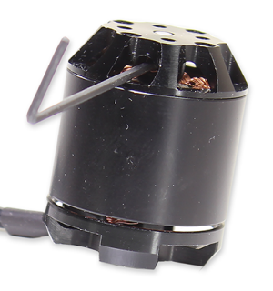
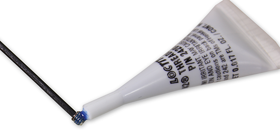
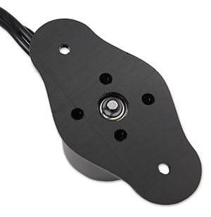
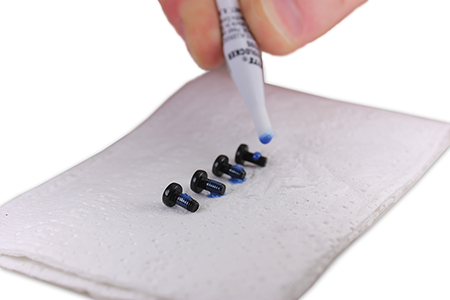
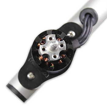
For users with V3 kits purchased before February 2016, and/or users with motors that have only one (1) set screw, please complete this step. Here you will apply Loctite® to the motor set screws to prevent them from loosening during flight and potentially causing equipment failure.
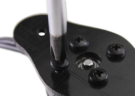
Using the hex key, carefully remove the motor set screw from each motor. The screws may be very tight; be careful not to break your hex key.
Tip! To open the Loctite® twist off the cap. When you are done, use the other end of the cap to seal the Loctite®, you’ll need it a few more times in the assembly process.
3. Allow the Loctite® to set for 10 minutes; it will fully cure in 24 hours.
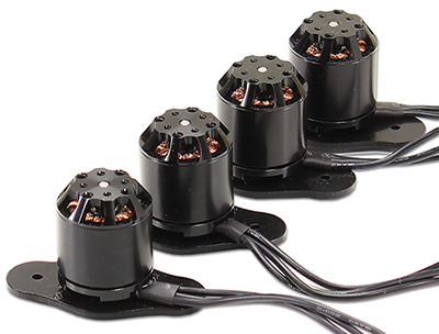
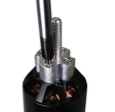
Before the motors can be attached to the Booms, they need to be connected to the Motor Mounts, which are one of the sacrifical parts of the ELEV-8 v3.
Sacrificial parts are intentionally engineered to fail under excess mechanical stess. They are engineered to fail first, thus protecting other parts of the system, just as an elecrrical fuse protects an elecrical circuit. In this case, the motor mount is engineered to to break before the motor is damaged in most (but not all) crashes, since it is less expensive and easier to replace than the motor.
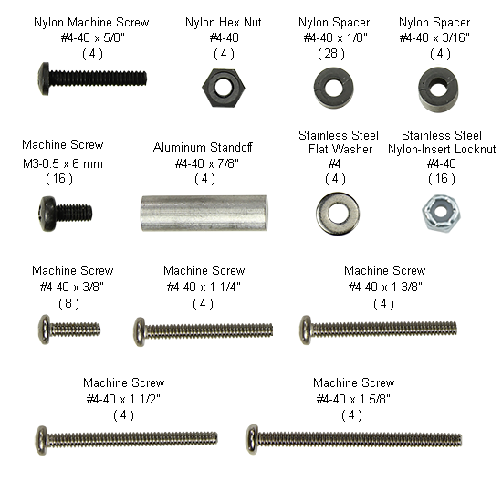
Tip! For your reference, wherever hardware is included in a Parts list, just click on the item link to open this image in a new window.
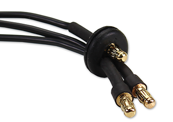
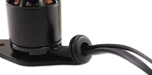
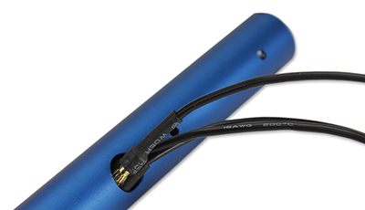
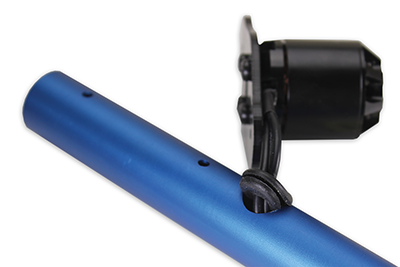
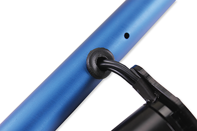
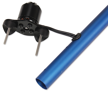
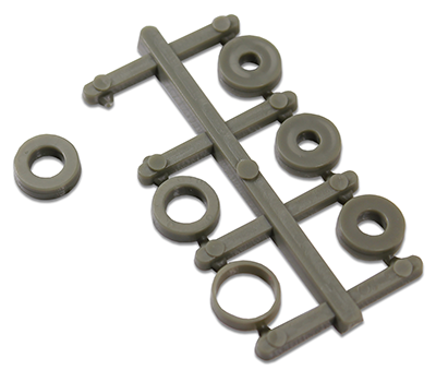
The extension wires are feed through the booms to protect them, and it’s easiest to do so before the motors are mounted. Grommets are used to protect the wires from the sharp edges of the holes
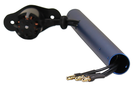
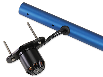
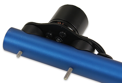
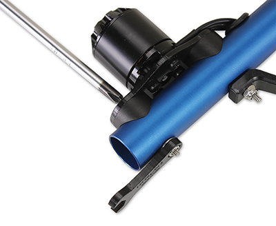
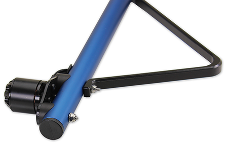
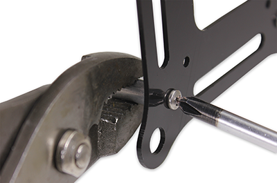
Now you will be fastening the motor mounts to the booms and attaching one side of the landing gear.
*When determinig which machine screw to use, use the screws with a length that is equal to or just shorter than the length listed. Industry standard tolerance for machine screws allows them to be up to 1/16″ shorter than their numerical size.
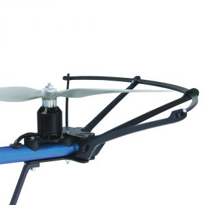
Before you begin, view the ELEV-8 Prop Guard Kit tutorial videos, and decide whether you will add this accessory to your quadcopter. It is highly recommended to help reduce repairs and property damage if you are learning to fly. If yes, then assemble each section according to the video, and attach to each boom as you proceed from Step 3 below, but using the longer screws provided with the Prop Guard kit.
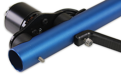
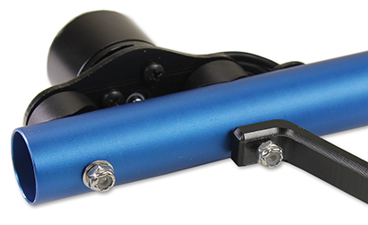
If you elected to use the Prop Guard Kit, each boom will instead look like this:
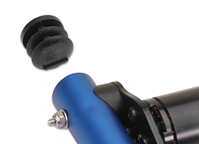
In the final step of boom assembly, you’ll be fitting plastic caps to the end of the booms, which will help protect them from impact and gives the ELEV-8 a cleaner look!
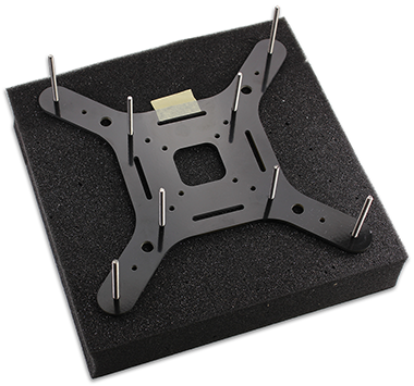
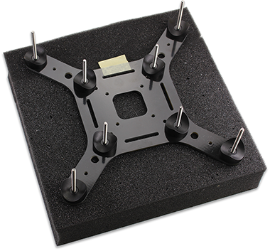
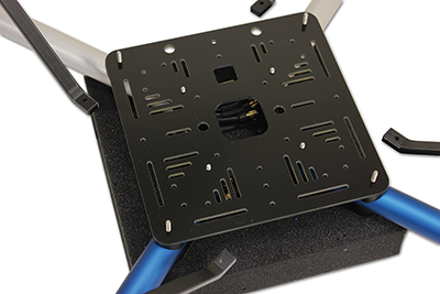
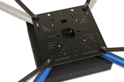
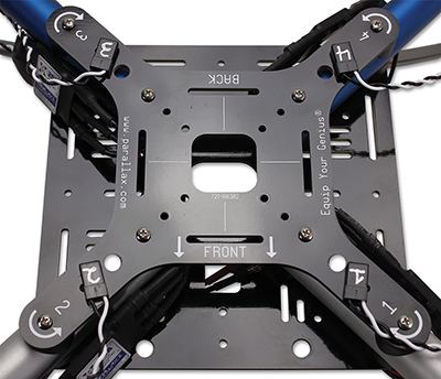
Chassis assembly starts with laying out the hardware and placing the top chassis plate upside down on an elevated surfase, so that the booms can be positioned level in the next step.

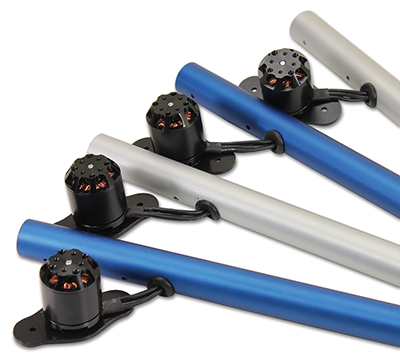
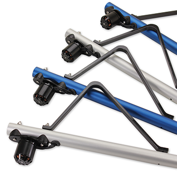
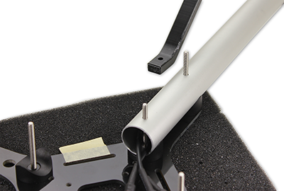
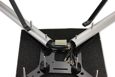
Now you will carefuly lay out the booms to ensure the colors are placed in the corrrect orientation. The clear anodized (appear silver in color) booms will be at the front, and the blue anodized booms will be at the rear.

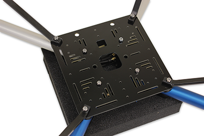
With everything prepared, you will now carefuly attach the bottom chassis plate. Some patience will serve you well here. The ELEV-8 v3 is designed with tight tolerances to achieve the strongest and most rigid from possible, so it may take a miniute or two to get everything lined up properly.
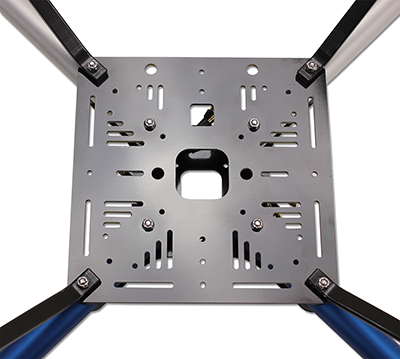
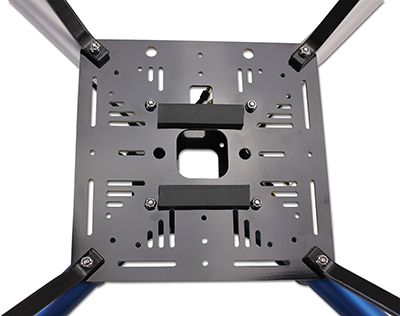
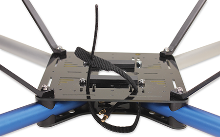
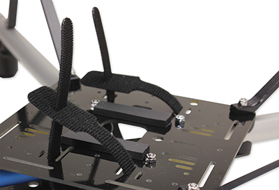
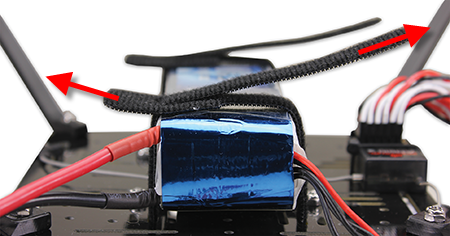
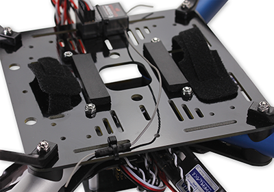
While the two hook and loop straps normally secure the battery well, some users prefer the extra security provided by the addition of two foam pads underneath the battery. Adding the foam pads more firmly secures the battery in place and also works to prevent slipping.
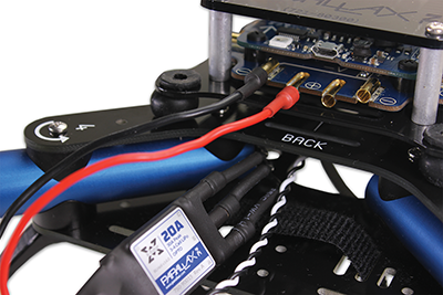
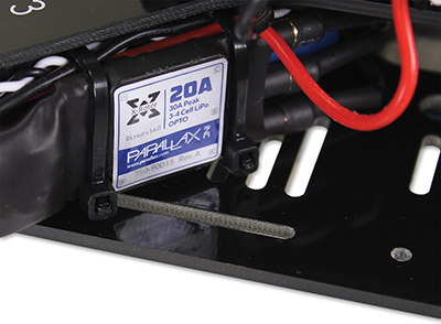
You will connect the electronic speed controllers (ESCs) to the motor cables. Don’t secure (zip-tie or otherwise) the ESCs just yet; that will be done after the motor spin direction has been configured in Secton 7, since it may be necessary to unplug the ESCs at that time.

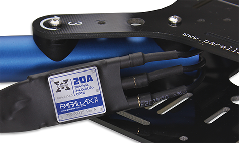
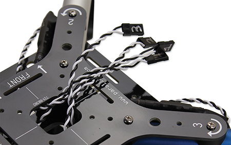
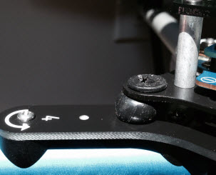
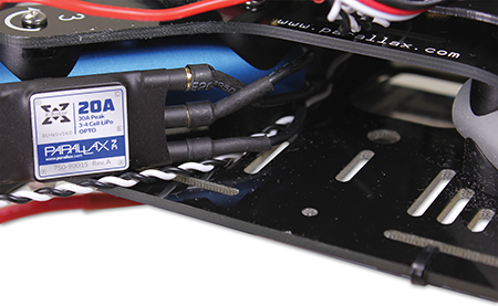
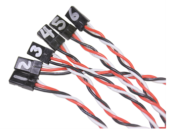
As the number of wires and connections grows, it becomes increasingly easy to make minor mistakes in setting up the electrical connections. To minimize the risk of such a mishap, you will now label the ESCs with the motor numbers.
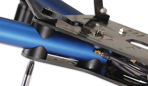
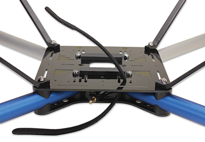
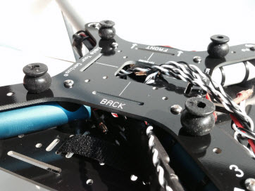
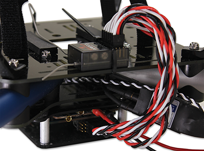
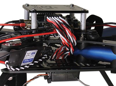
For a cleaner apperance and better protection, route the signal cables for the ESCs up through the center of the top chasis plate.
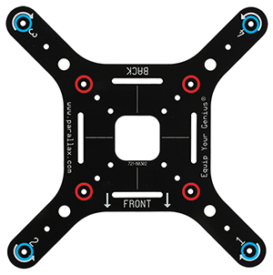
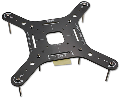
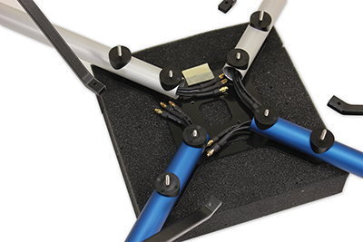
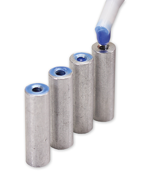
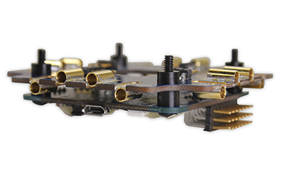
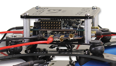
Assembly of the Isolation System starts with bolting the aluminium standoffs to the Isolation Plate. These bolts will face upwards, so it is best practice to use some method of threadlocking to keep them secure. Here, we will be using Loctite®.
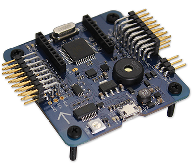
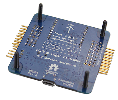
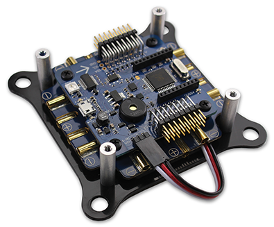
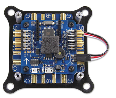
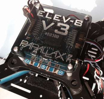
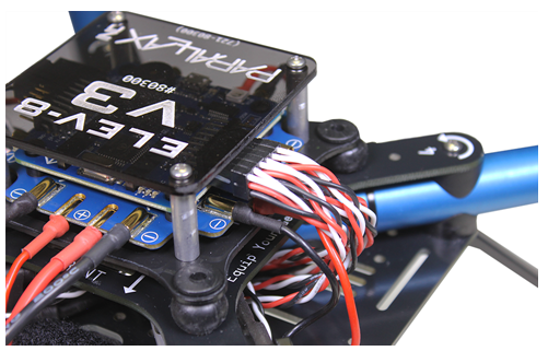
It’s now time to secure the flight controller and power distribution board. Nylon (plastic) hardware is used here to reduce the risk of damage to the boards from over-tightening, and beacue they are non-conductive.
Warning! The ELEV-8 Flight Controller is a sensitive piece of elecrical equipment. Handle it with care, and do not expose it to water or static elecricity.
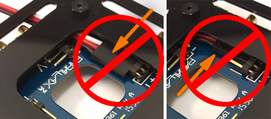
Before the Isolation Assembly is attached to the chassis, the cable that will provide power the the flight controller is attached.
WARNING: If the 3-pin cable connecting the flight controller to the power distribution board is plugged into the 3-pin header incorrectly, it will destroy your flight controller when you connect your battery!
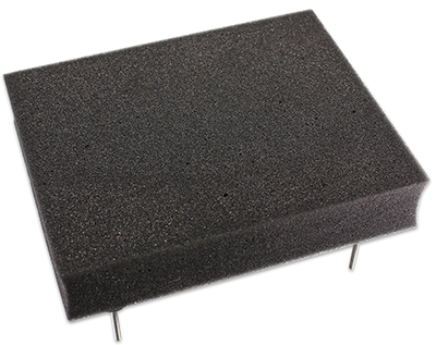
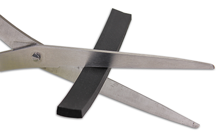
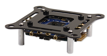
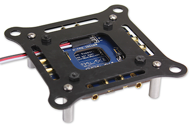
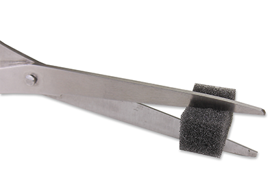
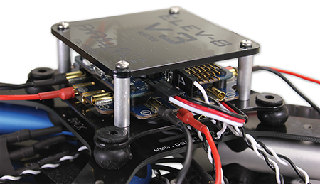
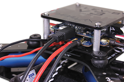
The barometric pressure sensor on the flight controller (FC) is sensitive to sunlight and wind, so a piece of open-cell foam will be placed over it to protect it. The foam will shield it from direct light and high speed airflow, while still allowing enough air to pass through to accuratly measure the air pressure. The flight controller cover will further shield the electronics while still allowing you to view the flight controller.
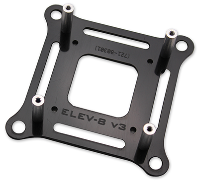
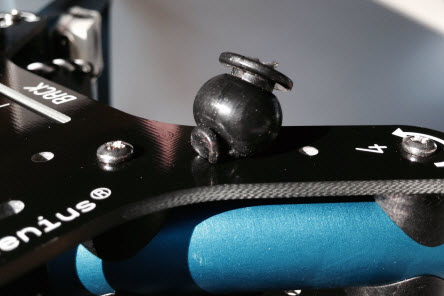
The Isolation System dampens vibrations created by the propellers to improve the performance of the flight controller.

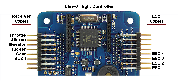
With all the major components of the ELEV-8 v3 installed, the wiring process begins with connecting the ESCs.
WARNING: Reversing the polarity may cause permanent damage to the ESCs and other components. Check your connections carefully!
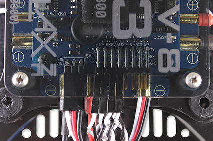
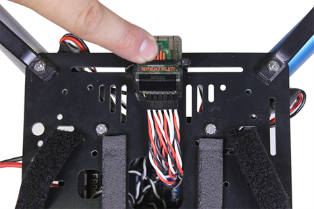
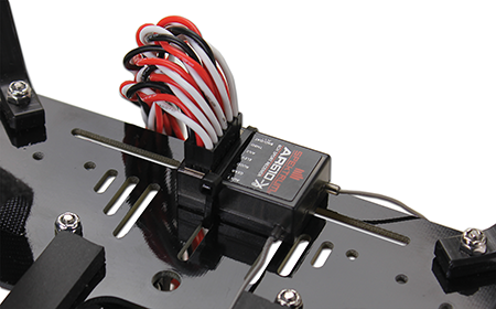
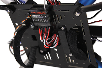
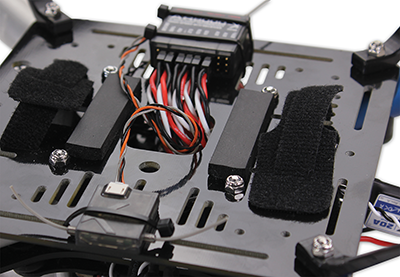
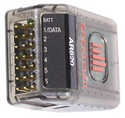
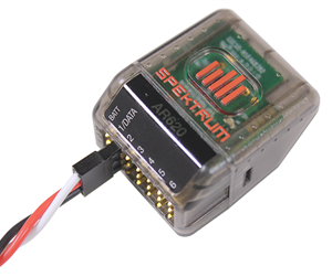
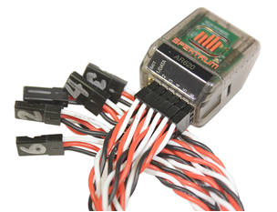
In this step you will connect the signal cables for the receiver to both the ELEV-8 Flight Controller and the receiver, and then mount the reciever to the chassis.
Instructions are provided for customers using the Spektrum SPMAR620 receiver (Step 19a) or the Spektrum AR610/AR8000 receiver (Step 19b). Please choose the set of instructions that match your receiver model to continue. If you are using a different receiver, your process may vary and you should consult your receiver manual.
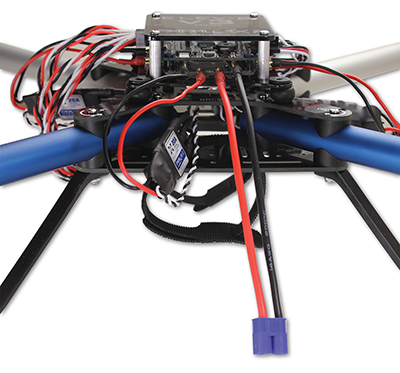
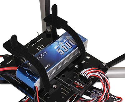
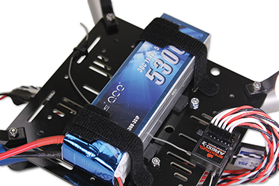
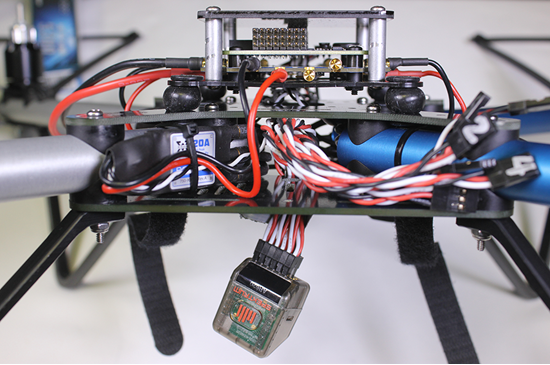
It is now time to install the battery underneath the chassis. Thanks to the hook-and-loop straps, it can be easily removed for charging and storage.
WARNING: Reversing the polarity may cause permanent damage to the battery and other components. Check your connections carefully!
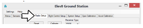
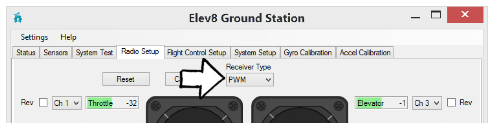
Radio transmitters come with an overwhelming array of settings. This step will guide you through configuring your transmitter so that it can properly control your ELEV-8 v3. Below is a table of transmitter setting recommendations for flying the ELEV-8 v3, regardless of transmitter selection. You will also bind your transmitter to your receiver, which enables your particular transmitter to control your particular receiver for the ELEV-8 v3.
| Box Model Type | ACRO (Plane Mode) |
|---|---|
| End Point (Travel) Adjustment | Spektrum: 125% for all channels Others: Unknown (let us know what works for you!) |
| Channel Reverse | Spektrum: Aileron, Rudder, Gear, Aux 1 Others: Unknown (let us know what works for you!) |
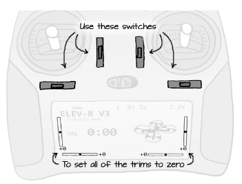
| Trims & Sub-Trims | Centered |
| Dual-Rates (D/R) | 100% (Disabled) |
| Exponential | None |
| Gear Channel Control | 3-Position Switch |
We’ll guide you through making these settings on a Spektrum DXe, DX6, & DX7 in the following instructions.
To get started, choose the your transmitter type from the list below. Once you have finished configuring your transmitter, scroll down the page to find the receiver binding instructions.
For other transmitters/receivers, refer to the literature provided by the manufacturer. If you are new to radio control, many of these terms may be foreign to you. For the sake of brevity we won’t go into those terms now, but we do strongly recommend that you take the time to research any term or concept that is unfamiliar. Please remember to read and abide by your RC transmitter’s instruction manual, as every system is different.
If your transmitter has never been used, proceed directly to the binding instructions. If your transmitter has been used, make sure that all settings are set to their default value and all trims are centered, then proceed to the binding instructions.
Notice that the DXe has a Dual Rate (“D/R”) Switch, which changes the sensitivity of the joysticks. You will want to keep this switch in the “Hi” at all times, including during GroundStation transmitter calibration. Failure to do so may cause unexpected behavior and inhibit your ability to arm/disarm the ELEV-8. If you have the DXe Programming cable, we recommend you disable this feature.
In order to configure your ELEV-8 Flight Controller in the next step, you will need to install three small pieces of software.
You will need a Windows or Mac computer and two pieces of software, choosing the version for your operating system. You will also need the most recent version of the Flight controller firmware.
To ensure your ELEV-8 Flight Controller is running the latest and greatest firmware (and becasue some units don’t ship with firmware), you will now install the firmware on your ELEV-8 Flight Controller.
With the latest firmware now loaded onto your ELEV-8 Flight Controller, you will optimize it for your particular RC radio transmitter.
Before proceeding, make sure that you have carefully followed the instructions in Step 21 for configuring your radio, or by carefully following the manufacturers instructions for setting up your transmitter.
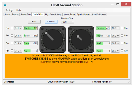
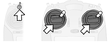
During calibration, only actuate switches for the axullary channels. Do not move Dual-Rate (D/R) switches (leave them in high or disable them), or Throttle Arm/Disarm switches (leave in “Arm” postion). This is especially important for the Spektrum DXe Transmitter.

Before moving on, the ESCs (electronic speed controllers) will need to be calibrated. This process tells the ESCs the minimum and maximum throttle range sent from the flight controller to the ESCs. If this is not done before flight, your motors may not respond correctly – causing unstable or unpredictable flight.
This calibration process is done using the Throttle Calibration button and by disconnecting and reconnecting your flight battery in a specific manner: you will need to have a charged battery and be able to connect and disconnect it during this process. Again, make sure that your propellers have been removed.
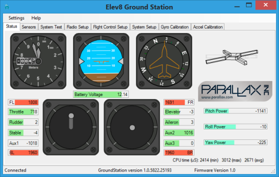
The Parallax GroundStation application will visually indicate when to unplug or plug in your battery during this calibration process. Watch for screen indicators.
To hear what the series of beeps in instructions 4 and 5 should sound like during a successful calibration, download this .zip file containing a wav sound file for each instruction.
Now you will check that the motors are spinning in the desired direction. If any motors are spinning in the wrong direction, it is a simple matter of switching any two of the ESC outputs to fix the issue.
Warning! Propellers should not yet be installed on your ELEV-8 v3. If you have done so, remove them now before continuing.
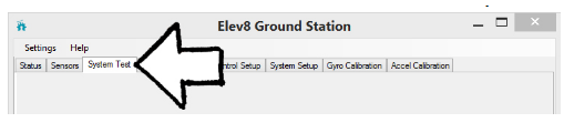
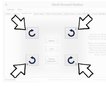
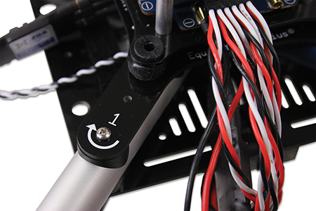
If the motor spun in the correct direction (as indicated by the markings on your top chassis plate, shown below), skip to step 8. If it did not, follow steps 5-7.
If the Motor Did Not Spin in the Correct Direction:
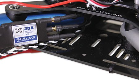
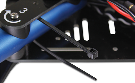
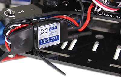
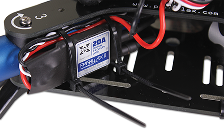
With the motors all spinning the correct directions, you can now secure the ESCs so that they don’t move during flight. By securing them to the booms, they won’t get in the way of folding up your ELEV-8 for transport if you ever choose to do so.
Instructions:
Before installing the propellers, you need to perform a radio control system range check, which will ensure that your transmitter and receiver are working properly. This step is often overlooked, but failing to perform this check can be have significant, and often dangerous, consequences.
(if you have a Spektrum DXe transmitter, skip this step)
You should have full control of your ELEV-8 from this distance. If you are unable to arm/disarm your ELEV-8 v3 as described below, do not fly! Some component of your system is malfunctioning and you should begin troubleshooting.
At Parallax, we are very often asked about the range of the RC Equipment we use. Unfortunately, there is no simple answer, as most Radio Control manufacturers (including Spektrum, which we use with the ELEV-8 v3) do not publish any information on operating ranges for their equipment, and Parallax cannot accept the liability associated with providing any such information ourselves. However, we can provide some basic guidelines. The operating range of RC equipment can vary widely, and is dependent on many factors, including (but not limited to) weather, receiver mounting position and orientation, transmitter orientation, aircraft size and materials, obstructions between or near transmitter and receiver, ambient radio traffic, transmitter and receiver condition, power, and sensitivity, and finally, distance between transmitter and receiver. With all of these variables, it’s important to read and follow all instructions provided by the manufacturers of RC equipment to avoid signal loss. Generally speaking “Parkflyer” type RC Equipment (such as the Spektrum DXe and DX6 Transmitters with AR610 Receiver) is only intended to be used on small aircraft flying at low speeds no more than a few hundred (300-500) feet line of sight from the operator (though they may work at greater distances). More high-end RC equipment (such as the Spektrum DX7 and DX8 Transmitters with AR8000 Receiver) may have far greater ranges, possibly well beyond your line of sight.
WARNING FOR SPEKTRUM DXE USERS: For ELEV-8 Flight Controller firmware versions prior to v1.1, switching the disarm swtich will NOT actually disarm the quadcopter, but just temporarily stop the motors. Use the Ground Station software to view the version number of the ELEV-8 Flight Controller firmware.
Only arm your ELEV-8 v3 when it is safe to do so. When the ELEV-8 v3 is armed, the propellers spin at low throttle – but they can still cause injury even at their lowest speed.
The ELEV-8 v3 currently has two flight modes, Stability and Manual. These modes determine the flight characteristics of the ELEV-8 v3. Manual Mode gives full control of the sUAV to the operator. Stability Mode helps the operator fly steadily by smoothing and limiting the operator’s input.
When the ELEV-8 v3 is unarmed, the RGB LED on the flight controller will be green. There is also a different color that flashes to indicate the flight mode (gear). The LED’s flash color pattern indicates the ELEV-8 v3’s Status and Mode:
Disarmed (Stability Mode – Green with Blue Blink):
Disarmed (Manual Mode – Green with Orange Blink):

To arm the ELEV-8 v3, make sure that the Gear Switch is in the correct mode, and then push and hold the transmitter sticks down and to the center:
![]()
The RGB LED on the flight controller will turn yellow: After 1 second, the flight controller will beep, the RGB LED will turn red with a mode color blink, and the propellers will spin at low throttle:
Armed (Stability Mode – Red with Blue Blink):

Armed (Manual Mode – Red with Orange Blink):
To disarm the ELEV-8 v3, push and hold the transmitter sticks down and away from the center:
![]()
The RGB LED on the flight controller will turn yellow. After 0.5 seconds, the flight controller will beep, the RGB LED will turn green with a mode color blink, and the propellers will stop spinning.
Brushless motors sometimes experience a phenomenon known as slip. When a motor slips, it spins slower and in the wrong direction. If this occurs disarm and re-arm, and confirm the issue has been fixed. If you skip this and quickly throttle up, you may not notice the issue until your quad just lifts off the ground and instantly flips.
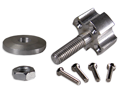
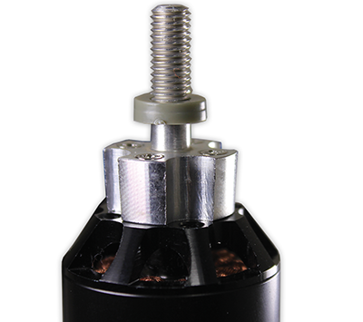
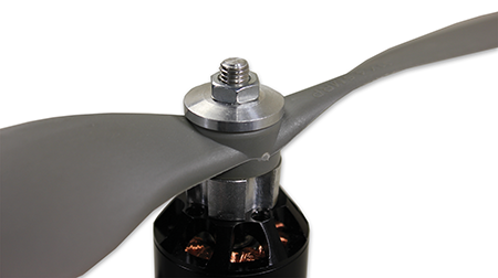
The Propeller adapters allow you to easily attach and remove the Propellers, and ensure that they stay centered on the Motors.
STOP!! Propeller blades can cut skin. Do not install propellers until you are ready to fly in a properly prepared indoor OR outdoor flying area. Never install propeller blades on a quadcopter in a classroom or a bench testing area. Never connect the flight controller to a computer if the propeller blades are installed.
Attaching the Propellers in the wrong positions is the #1 most common mistake, so follow the directions below carefully!
WARNING: Do not install the propellers until you have gone through every step of the Assembly Guide.
Congratulations on completing the assembly of your ELEV-8 v3 Quadcopter! We know you are probably anxious to fly it, so please head over to the How to Fly a Multirotor sUAV tutorial, where you will learn how to fly your ELEV-8 v3. PLEASE DO NOT attempt to fly your ELEV-8 v3 until you have read through both the How to Fly a Multirotor sUAV and UAV Safety, Laws, and Good Citizenship tutorials, as you could put yourself and others needlessly at risk. (For example, the Flying Guide contains important information on how to identify and switch between flight modes).
In this section, you’ll be assembling the four booms, or “arms” for your ELEV-8 v3.
Warning! As tempting as it may be, DO NOT attach the propellers or propeller adapters to the motor yet. In fact, you won’t need them until the very last step, so go ahead and stash them away for the moment.
This section will take approximately 1 to 2 hours, depending on your skill level and equipment.
Tip! For your reference, wherever hardware is included in a Parts list, just click on the item link to open this image in a new window.
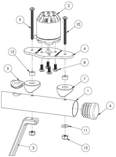
A PDF of the above drawing is available for download here.
In this section, you will assemble the ELEV-8 v3 Quadcopter chassis, following the four steps below. This section will take approximately 0.5 to 1.5 hours, depending on your skill level and equipment.
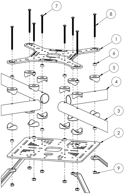
A PDF of the above drawing is available for download here.
In this section, you will connect the electronic speed controllers (ESCs), following the 3 steps below.
This section will take approximately 10 to 30 miniutes, depending on your skill level and equipment.
In this section, you will make the Isolation Assembly, following the 4 steps below.
This section will take approximately 15 to 60 miniutes, depending on your skill level and equipment.
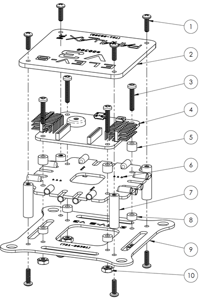
A PDF of the above drawing is available for download here.
In this section, you will install the isolation assembly and electronics in your ELEV-8 v3 Quadcopter, following the 4 steps below.
This section will take approximately 30 to 60 minutes, depending on your skill level and equipment.
In this section, you will configure your transmitter, install the GroundStation software, and update and configure your flight controller firmware, follwing the 4 steps below.
This section will take approximately 1 to 2 hours, depending on your skill level and equipment.
With Parallax GroundStation software now installed on your computer, you can use it calibrate the throttle range of your ESCs and check the spin direction of your motors before mounting your ESCs to the booms, as you will do in the this section’s three steps.
This section will take approximately 20 to 60 minutes to complete, depending on skill level and equipment.
In this section, you will conduct some final testing of your ELEV-8 v3 Quadcopter to ensure it is functioning properly and then install the propeller adapters and (finally) the propellers.
BEFORE continuing, please be sure that you have read the entirety of the UAV Safety, Laws, and Good Citizenship guide; it contains very important information to keep you, your ELEV-8, and the public safe and legal. DO NOT SKIP THIS!
The owner, operator, and pilot of every ELEV-8 v3 are to abide by all laws, regulations, and guidelines, including, but not limited to, those detailed in the UAV Safety, Laws, and Good Citizenship guide. Reading and abiding by the entire UAV Safety, Laws, and Good Citizenship document could help prevent property damage, personal injury, prosecution, and fines.
At the end of the Step 30, you will be you will be directed to the How to Fly a Multirotor sUAV tutorial, where you will learn to fly your ELEV-8 v3. DO NOT attempt to fly your ELEV-8 v3 until you have read through both this and the UAV Safety, Laws, and Good Citizenship tutorials, as you may put yourself and others needlessly at risk.
This section will take approximately 15 minutes to 45 minutes, depending on your skill level and equipment.
Note: If you’re using a Spektrum SPMAR620 receiver, please follow instructions in Step 19a.
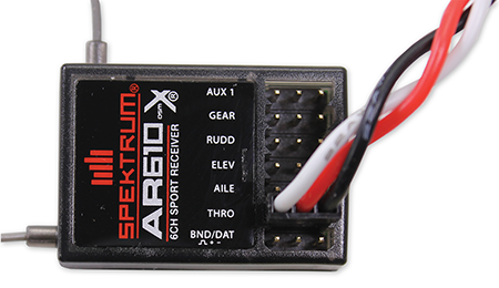
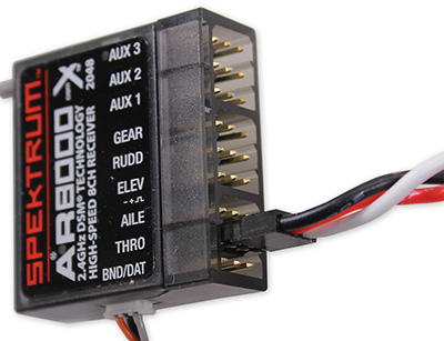
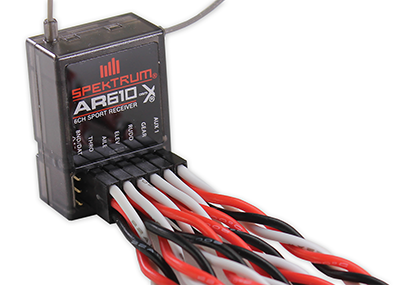
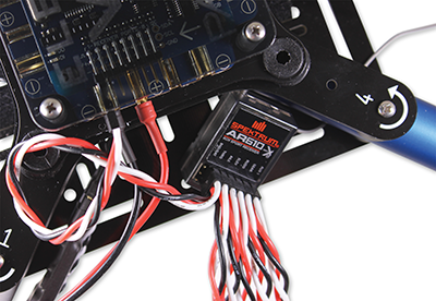
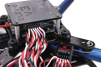
Note: If you’re using a Spektrum AR610 or AR8000 receiver, please follow instructions in Step 19b.

