First, get a Shield-Bot!
Then, follow the tutorial!
Check out each Chapter Summary (1, 2, 3, 4, 5, 6, 7, 8) to see what STEM skills and concepts your students will soak up. If you use the BOE Shield-Bot in your classroom curriculum, we’d love to hear all about it. Email editor@parallax.com.
No problem! The activities and projects in this text start with an introduction to the BOE Shield-Bot’s brain, the Arduino® Uno. Then, you will build, test, and calibrate the BOE Shield-Bot. Next, you will learn to program the BOE Shield-Bot for basic maneuvers. After that, you’ll be ready to add different kinds of sensors, and write sketches to make the BOE Shield-Bot sense its environment and respond on its own.
This is a good place to start! The code examples introduce Arduino programming concepts little by little, with each example sketch explained fully.
See how each electronic component is used with a circuit symbol and part drawing. Traditional schematics next to wiring diagrams make it easy to build the circuits.
The Shield-Bot is a variation of the original Boe-Bot® robot with its BASIC Stamp® 2 brain, shown below. It was introduced by Parallax Inc. in 1999 and enjoyed instant popularity with schools as for their robotics, electronics, programming and physics programs. Today, the Boe-Bot Robot Kit and its accompanying text continues to be in demand for STEM courses, because PBASIC is a very easy language for a first-time text-based programming experience.
The Arduino microcontroller arrived on the scene in 2005 and its popularity grew through the DIY (do-it-yourself) hobby community. Parallax teamed up with SimplyTronics to design the Board of Education® Shield, which makes the Arduino hardware compatible with the Boe-Bot chassis. The Arduino can do the same tasks as the BASIC Stamp, though in a slightly different way, but it was still straightforward to rewrite the original Robotics with the Boe-Bot to support the Shield-Bot. This gives the Arduino hobby community the opportunity to wrap a robotics shield around an Uno. It also gives teachers a different programming language option for working with Parallax robots.
This book is designed to promote technology literacy through an easy introduction to microcontroller programming and simple robotics. Are you a middle-school student? You can be successful by following the check-marked instructions with your teacher’s support. If you are a pre-engineering student, push yourself a little farther, and test your comprehension and problem-solving skills with the questions, exercises and projects (with solutions) in each chapter summary. If you are an independent learner working on your own, go at your own pace and check in with Parallax’s Robotics forum if you get stuck.
If you are an educator, feel free to contact our team at education@parallax.com for support deploying the Shield-Bot in your STEM program.
Andy Lindsay joined Parallax Inc. in 1999, and has since authored more than a dozen books, including What’s a Microcontroller? as well as numerous articles and product documents for the company. The original Robotics with the Boe-Bot that is the inspiration for this book was designed and updated based on observations and educator feedback that Andy collected while traveling the nation and abroad teaching Parallax Educator Courses and events. Andy studied Electrical and Electronic Engineering at California State University, Sacramento, and is a contributing author to several papers that address the topic of microcontrollers in pre-engineering curricula. When he’s not writing educational material, Andy does product and application engineering for Parallax.
The Parallax team assembled to prepare this edition includes: excellent department leadership by Aristides Alvarez, lesson design and technical writing by Andy Lindsay; cover art by Jen Jacobs; graphic illustrations by Rich Allred and Andy Lindsay; nitpicking, editing, and layout by Stephanie Lindsay.
Several customers helped test-drive this material. Thanks go to Gordon McComb for test-driving and technical feedback on the original chapter drafts. Special thanks also go to Matt Zawlocki and his Fall 2015 middle-school students for trying all of the example sketches with the Codebender browser-based editor.
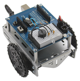
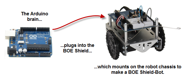
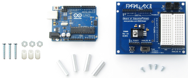
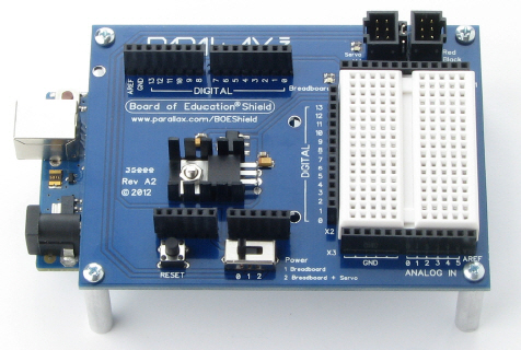
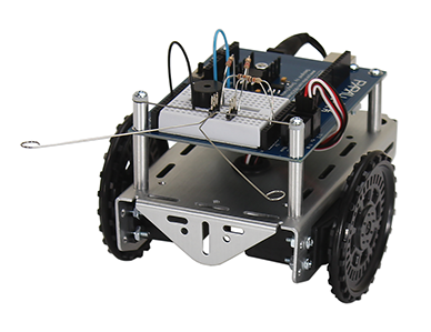
Parallax Inc.’s Shield-Bot robot is the focus of the activities, projects, and contests in this book. The Board of Education (BOE) Shield mounts on a metal chassis with servo motors and wheels. An Arduino Uno module—the programmable brain—plugs in underneath the BOE Shield.
The activities in this tutorial will guide you through building the mechanical parts and circuits that make the BOE Shield-Bot work. Then, you’ll write simple programs that make the Arduino and your robot do four essential robotic tasks:
To do the activities in this tutorial, you will need both software and software.
There are several hardware kit options for building a Parallax Shield-Bot.
The Arduino Uno is the preferred module for the Shield-Bot robot.
This tutorial has also been tested with a Duemilanove and original Mega. These Arduino modules automatically decide whether to draw power from USB or an external source (like the Shield-Bot’s battery pack).
If you have an older model Arduino, you may have to set its power selection jumper. (Don’t worry about this if you have an Uno, Duemilanove, or Mega.) The circuit is labeled PWR_SEL. It’s three pins with a small cover called a shunt that slides over two of three pins. For now, make the shunt cover the USB and center pins. Later, when you switch to using the Shield-Bot’s battery pack, move the shunt to cover the EXT pin and center pin instead.
This tutorial requires the Arduino language 1.0 or higher. There are several recommended software options for using this language.
If this is your first time using an Arduino, Activity #1 will help you get started with your choice of software, connect your hardware, and test your programming connection. The rest of this chapter includes a series of example programs (called sketches) that introduce common programming concepts. The sketches will do some of the most basic yet important things for a robot:
These examples don’t require interaction with external circuits. In later chapters you will start building circuits and make your robot move. You will also learn additional programming techniques like keeping lists of values and writing pieces of reusable code.
Before continuing, is a good idea to make sure you have all of the correct parts to build and program your Shield-Bot.
Use the pictures and part numbers on the following pages to double-check the robot chassis parts, small hardware, and electronic components. If you need anything, contact sales@parallax.com.
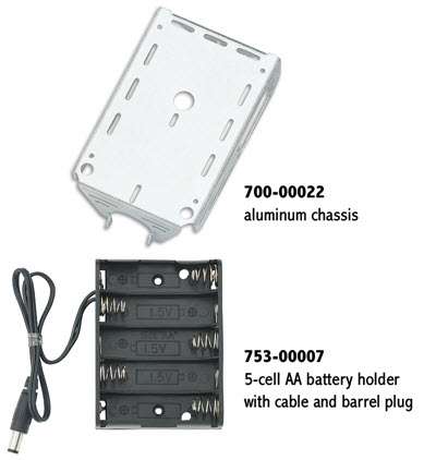
In Chapter 3, you will build your Shield-Bot on an aluminum chassis. It will use 5 AA batteries for a power supply.
Wheels will connect to servo motors to drive the Shield-Bot, and a tail wheel ball will attach to the chassis with a cotter pin.
Note: Wheel and tire styles have changed over time. Yours may look different, that’s okay. You will see more than one style shown in this tutorial.
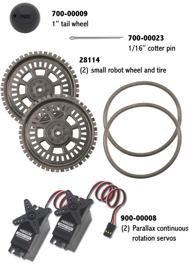
A bag of hardware supplies everything you will need to assemble your robot in Chapter 3. Note that both regular nuts and Nylon-core locknuts are provided. This kit is also available separately as the Robot Hardware Refresher Pack.

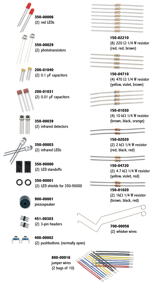
A bag of electronic components is included with your kit. You will use these parts to build circuits in almost every chapter of this book. This kit is also available separately as the Boe-Bot and Shield-Bot Refresher Pack.
Note: Your Infrared Receivers may look different, since suppliers change over time. If you ever need replacements, be sure to order the Infrared Receiver for Boe-Bot and Shield-Bot (#350-00039).
Arduino programs are called sketches. If you type in all of the example sketches by hand, you’ll develop your programming skills faster. But, sometimes it’s helpful to have tested sketches on hand for troubleshooting circuts or finding bugs. So, all of the complete sketches are provided for your use below.
If this is your first time working with the Arduino system, you will need to set up a programming software option: Arduino IDE, Arduino Web Editor, or Codebender : edu.
Arduino IDE software and drivers install on your Windows, Mac, or Linux computer. You do not need to be online to use it.
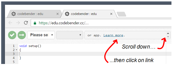
Codebender : edu is an online programming tool that works on Windows, Mac, Linux, or Chromebook, in a Chrome or Firefox browser session. You need to install a browser plug-in and drivers, and be online to use it. Registration for an account that may be shared in a classroom is required.
To get started using Arduino Web Editor instead of the Arduino IDE, click here.
To get started using Codebender instead of the Arduino IDE, click here.
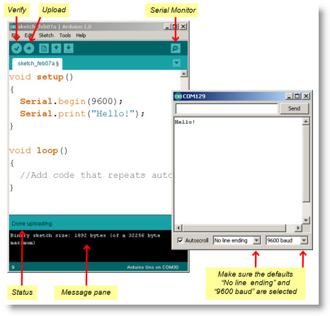
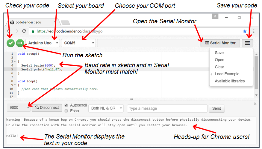
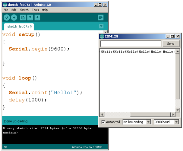
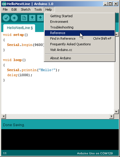
Here is a screen capture of the Arduino Development Environment edit pane on the left, containing a simple sketch that sends a “Hello!” message to the Serial Monitor window on the right.
void setup()

{
  Serial.begin(9600);
  Serial.print("Hello!");
}

void loop()
{
  //Add code that repeats automatically here.
}
Now you are ready to see How the Hello Sketch Code Works.
Now that you have an account to use with codebender : edu, and have installed the required plug-in and drivers, it is time to try a sketch!
void setup()

{
  Serial.begin(9600);
  Serial.print("Hello!");
}

void loop()
{
  //Add code that repeats automatically here.
}
Later, you can choose Open from this menu to re-open your sketch. Or, navigate to the un-zipped example code archive you downloaded previously to open sketches used in this book.
To keep things simple, the rest of the Shield Robot tutorials will feature directions and screen-captures for the Arduino IDE software.
A function is a container for statements (lines of code) that tell the Arduino to do certain jobs. The Arduino language has two built-in functions: setup and loop. The setup function is shown below. The Arduino executes the statements you put between the setup function’s curly braces, but only once at the beginning of the program.
In this example, both statements are function calls to functions in the Arduino’s built-in Serial pre-written code library: Serial.begin(speed) and Serial.print(val). Here, speed and val are parameters, each describing a value that its function needs passed to it to do its job. The sketch provides these values inside parentheses in each function call.
Serial.begin(9600); passes the value 9600 to the speed parameter. This tells the Arduino to get ready to exchange messages with the Serial Monitor at a data rate of 9600 bits per second. That’s 9600 binary ones or zeros per second, and is commonly called a baud rate.
Serial.print(val); passes the message “Hello!” to the val parameter. This tells the Arduino to send a series of binary ones and zeros to the Serial Monitor. The monitor decodes and displays that serial bitstream as the “Hello!” message.
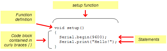
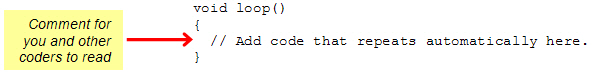
After the setup function is done, the Arduino automatically skips to the loop function and starts doing what the statements in its curly braces tell it to do. Any statements in loop will be repeated over and over again, indefinitely. Since all this sketch is supposed to do is print one “Hello!” message, the loop function doesn’t have any actual commands. There’s just a notation for other programmers to read, called a comment. Anything to the right of // on a given line is for programmers to read, not for the Arduino software’s compiler. (A compiler takes your sketch code and converts it into numbers—a microcontroller’s native language.)
What is void? Why do these functions end in ()? The first line of a function is its definition, and it has three parts: return type, name, and parameter list. For example, in the function void setup() the return type is void, the name is setup, and the parameter list is empty – there’s nothing inside the parentheses (). Void means ‘nothing’—when another function calls setup or loop, these functions would not return a value. An empty parameter list means that these functions do not need to receive any values when they are called to do their jobs.
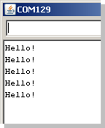
Microcontroller programs generally run in a loop, meaning that one or more statements are repeated over and over again. Remember that the loop function automatically repeats any code in its block (the statements in between its curly braces). Let’s try moving Serial.print(“Hello!”); to the loop function. To slow down the rate at which the messages repeat, let’s also add a pause with the built-in delay(ms) function.
The added line delay(1000) passes the value 1000 to the delay function’s ms parameter. It’s requesting a delay of 1000 milliseconds. 1 ms is 1/1000 of a second. So, delay(1000) makes the sketch wait for 1000/1000 = 1 second before letting it move on to the next line of code.
How about having each “Hello!” message on a new line? That would make the messages scroll down the Serial Monitor, instead of across it. All you have to do is change print to println, which is short for ‘print line.’
Still have questions? Try the Arduino Language Reference. It’s a set of pages with links you can follow to learn more about setup, loop, print, println, delay, and lots of other functions you can use in your sketches.
If you are using Codebender, go to https://www.arduino.cc/en/Reference/HomePage.
Variables are names you can create for storing, retrieving, and using values in the Arduino microcontroller’s memory. Here are three example variable declarations from the next sketch:
  int a = 42;
  char c = 'm';
  float root2 = sqrt(2.0);
The declaration int a = 42 creates a variable named a. The int part tells the Arduino software what type of variable it’s dealing with. The int type can store integer values ranging from -32,768 to 32,767. The declaration also assigns a an initial value of 42. (The initial value is optional, you could instead just declare int a, and then later assign the value 42 to a with a = 42.)
Next, char c = ’m’ declares a variable named c of the type char (which is for storing characters) and then assigns it the value ’m’.
Then, float root2 = sqrt(2.0) declares a variable named root2. The variable type is float, which can hold decimal values. Here, root2 is initialized to the floating-point representation of the square root of two: sqrt(2.0).
Now that your code has stored values to memory, how can it retrieve and use them? One way is to simply pass each variable to a function’s parameter. Here are three examples, where the Serial.println(val) function displays the value of the variable inside the parentheses.
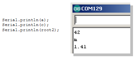
One nice thing about variable types is that Serial.println recognizes each type and displays it correctly in the serial monitor. (Also, the C++ compiler in the Arduino software requires all declared variables to have a type, so you can’t leave it out.)
// Robotics with the BOE Shield - StoreRetrieveLocal

void setup()
{
  Serial.begin(9600);

  int a = 42;
  char c = 'm';
  float root2 = sqrt(2.0);

  Serial.println(a);
  Serial.println(c);
  Serial.println(root2);
}

void loop()
{
  // Empty, no repeating code.
}
ASCII stands for American Standard Code for Information Exchange.
It’s a common code system for representing computer keys and characters in displays. For example, both the Arduino and the Serial Monitor use the ASCII code 109 for the letter m. The declaration char c = ’m’ makes the Arduino store the number 109 in the c variable. Serial.println(c) makes the Arduino send the number 109 to the Serial Monitor. When the Serial Monitor receives that 109, it automatically displays the letter m. View ASCII codes 0–127.
There are two ways to prove that the ASCII code for ’m’ really is 109. First, instead of declaring char c = ’m’, you could use byte c = ’m’. Then, the println function will print the byte variable’s decimal value instead of the character it represents. Or, you could leave the char c declaration alone and instead use Serial.println(c, DEC) to display the decimal value c stores.
So, do you think the letters l, m, n, o, and p would be represented by the ASCII codes 108, 109, 110, 110, 111, and 112?
So far, we’ve declared variables inside a function block (inside the function’s curly braces), which means they are local variables. Only the function declaring a local variable can see or modify it. Also, a local variable only exists while the function that declares it is using it. After that, it gets returned to unallocated memory so that another function (like loop) could use that memory for a different local variable.
If your sketch has to give more than one function access to a variable’s value, you can use global variables. To make a variable global, just declare it outside of any function, preferably before the setup function. Then, all functions in the sketch will be able to modify or retrieve its value. The next example sketch declares global variables and assigns values to them from within a function.
This example sketch declares a, c, and root2 as global variables (instead of local). Now that they are global, both the setup and loop functions can access them.
// Robotics with the BOE Shield - StoreRetrieveGlobal

int a;
char c;
float root2;

void setup()
{
  Serial.begin(9600);

  a = 42;
  c = 'm';
  root2 = sqrt(2.0);
}

void loop()
{
  Serial.println(a);
  Serial.println(c);
  Serial.println(root2);
  delay(1000);
}
There are lots more data types than just int, char, float, and byte.
Arithmetic operators are useful for doing calculations in your sketch. In this activity, we’ll focus on the basics: assignment (=), addition (+), subtraction (–), multiplication (*), division(/), and modulus (%, the remainder of a division calculation).
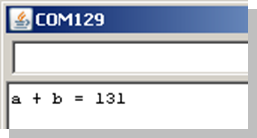
The next example sketch, SimpleMath, adds the variables a and b together and stores the result in c. It also displays the result in the Serial Monitor.
Notice that c is now declared as an int, not a char variable type. Another point, int c = a + b uses the assignment operator (=) to copy the result of the addition operation that adds a to b. The figure below shows the expected result of 89 + 42 = 131 in the Serial Monitor.
// Robotics with the BOE Shield - SimpleMath

void setup()
{
  Serial.begin(9600);

  int a = 89;
  int b = 42;
  int c = a + b;

  Serial.print("a + b = ");
  Serial.println(c);
}

void loop()
{
  // Empty, no repeating code.
}
If you need to work with decimal point values, use float.
If you are using integer values (counting numbers), choose byte, int, or long.
If your results will always be an unsigned number from 0 to 255, use byte.
If your results will not exceed –32,768 to 32,767, an int variable can store your value.
If you need a larger range of values, try a long variable instead. It can store values from ‑2,147,483,648 to 2,147,483,647.
You still have –, *, /, and % to try out!
So far, these lessons have processed integers values, which encompass negative and positive counting values. C language also handles floating point values, which allow you to process numbers with a decimal point and one or more digits to the right, much as a calculator does. Since the number of digits to the left or right of the decimal point is flexible, the decimal point’s position can “float” from one position to another as needed.
/*
  Floating Point Calculations.c

  Calculate and display circumference of a circle of radius = 1.0.
*/

#include "simpletools.h"                      // Include simpletools

int main()                                    // main function
{
  float r = 1.0;                              // Set radius to 1.0
  float c = 2.0 * PI * r;                     // Calculate circumference
  print("circumference = %f \n", c);          // Display circumference
}
This program knows that PI ≈ 3.1415926… because it is defined in the simpletools library. Inside the main function, a floating point variable named r is initialized to 1.0 with float r = 1.0.
After that, the circumference is calculated with c = 2.0 * PI * r.
Then, print(“circumference = %f \n”, c) displays the floating point value stored in c. Notice the new format placeholder: %f for a floating point value.
You can declare different variable types that can store different sizes and types of numbers.
| signed char | -127 to 127 |
| char | 0 to 255 |
| int | -2,147,483,647 to 2,147,483,647 |
| unsigned int | 0 to 4,294,967,295 |
| long | same as int |
| unsigned long | same as unsigned int |
| float | approx: 3.4X10-38 to 3.4X1038 with 6 digits of precision |
Let’s try calculating the area of a circle with a = π×r2, which is PI * r * r.
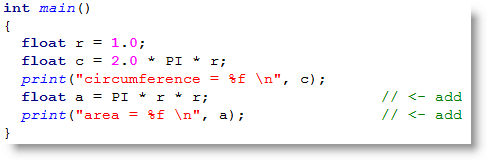
Keep in mind that you have to use 4.0/3.0 to get the floating point version of 4/3. You can also use pow(r, 3.0) to raise r to the third power.
Your BOE Shield-Bot will need to make a lot of navigation decisions based on sensor inputs. Here is a simple sketch that demonstrates decision-making. It compares the value of a to b, and sends a message to tell you whether or not a is greater than b, with an if…else statement.
If the condition (a > b) is true, it executes the if statement’s code block: Serial.print(“a is greater than b”). If a is not greater than b, it executes else code block instead: Serial.print(“a is not greater than b”).
// Robotics with the BOE Shield - SimpleDecisions

void setup()
{
  Serial.begin(9600);

  int a = 89;
  int b = 42;

  if(a > b)
  {
    Serial.print("a is greater than b");
  }
  else
  {
    Serial.print("a is not greater than b");
  }
}

void loop()
{
  // Empty, no repeating code.
}
Maybe you only need a message when a is greater than b. If that’s the case, you could cut out the else statement and its code block. So, all your setup function would have is the one if statement, like this:
void setup()
{
  Serial.begin(9600);

  int a = 89;
  int b = 42;

  if(a > b)
  {
    Serial.print("a is greater than b");
  }
}
Maybe your sketch needs to monitor for three conditions: greater than, less than, or equal. Then, you could use an if…else if…else statement.
if(a > b)
  {
    Serial.print("a is greater than b");
  }
  else if(a < b)
  {
    Serial.print("b is greater than a");
  }
  else
  {
    Serial.print("a is equal to b");
  }
A sketch can also have multiple conditions with the Arduino’s boolean operators, such as && and ||. The && operator means AND; the || operator means OR. For example, this statement’s block will execute only if a is greater than 50 AND b is less than 50:
 if((a > 50) && (b < 50))
  {
    Serial.print("Values in normal range");
  }
Another example: this one prints the warning message if a is greater than 100 OR b is less than zero.
if((a > 100) || (b < 0))
  {
    Serial.print("Danger Will Robinson!");
  }
One last example: if you want to make a comparison to find out if two values are equal, you have to use two equal signs next to each other: ==.
if(a == b)
  {
    Serial.print("a and b are equal");
  }
The rest of the statement gets left behind after it finds a true condition.
If the if statement turns out to be true, its code block gets executed and the rest of the chain of else ifs gets passed by.
Many robotic tasks involve repeating an action over and over again. Next, we’ll look at two options for repeating code: the for loop and while loop. The for loop is commonly used for repeating a block of code a certain number of times. The while loop is used to keep repeating a block of code as long as a condition is true.
A for loop is typically used to make the statements in a code block repeat a certain number of times. For example, your BOE Shield-Bot will use five different values to make a sensor detect distance, so it needs to repeat a certain code block five times. For this task, we use a for loop. Here is an example that uses a for loop to count from 1 to 10 and display the values in the Serial Monitor.
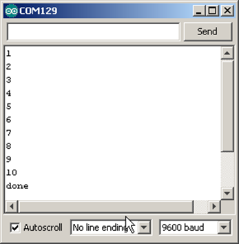
// Robotics with the BOE Shield - CountToTen

void setup()
{
  Serial.begin(9600);

  for(int i = 1; i <= 10; i++)
  {
    Serial.println(i);
    delay(500);
  }
  Serial.println("All done!");
}

void loop()
{
  // Empty, no repeating code.
}
The figure below shows the for loop from the last example sketch, CountTenTimes. It labels the three elements in the for loop’s parentheses that control how it counts.
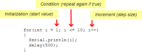
The first time though the loop, the value of i starts at 1. So, Serial.println(i) displays the value 1 in the Serial Monitor. The next time through the loop, i++ has made the value of i increase by 1. After a delay (so you can watch the individual values appear in the Serial Monitor), the for statement checks to make sure the condition i <= 10 is still true. Since i now stores 2, it is true since 2 is less than 10, so it allows the code block to repeat again. This keeps repeating, but when i gets to 11, it does not execute the code block because it’s not true according to the i <= 10 condition.
As mentioned earlier, i++ uses the ++ increment operator to add 1 to the i variable each time through the for loop. There are also compound operators for decrement —, and compound arithmetic operators like +=, -=, *=, and /=. For example, the += operator can be used to write i = i + 1000 like this: i+=1000.
for(int i = 5000; i <= 15000; i+=1000)
In later chapters, you’ll use a while loop to keep repeating things while a sensor returns a certain value. We don’t have any sensors connected right now, so let’s just try counting to ten with a while loop:
int i = 0;
  while(i < 10)
  {
    i = i + 1;
    Serial.println(i);
    delay(500);
  }
Want to condense your code a little? You can use the increment operator (++) to increase the value of i inside the Serial.println statement. Notice that ++ is on the left side of the i variable in the example below. When ++ is on the left of a variable, it adds 1 to the value of i before the println function executes. If you put ++ to the right, it would add 1 after println executes, so the display would start at zero.
 int i = 0;
  while(i < 10)
  {
    Serial.println(++i);
    delay(500);
  }
The loop function, which must be in every Arduino sketch, repeats indefinitely. Another way to make a block of statements repeat indefinitely in a loop is like this:
 int i = 0;
  while(true)
  {
    Serial.println(++i);
    delay(500);
 }
So why does this work? A while loop keeps repeating as long as what is in its parentheses evaluates as true. The word ’true’ is actually a pre-defined constant, so while(true) is always true, and will keep the while loop looping. Can you guess what while(false) would do?
The next sketch, CountToTenDocumented, is different from CountToTen in several ways. First, it has a block comment at the top. A block comment starts with /* and ends with */, and you can write as many lines of notes in between as you want. Also, each line of code has a line comment (starting with // ) to its right, explaining what the code does.
Last, two const int (constants that are integers) are declared at the beginning of the sketch, giving the names startVal, endVal, and baudRate to the values 1, 10, and 9600. Then, the sketch uses these names wherever it requires these values.
/*
 Robotics with the BOE Shield – CountToTenDocumented
 This sketch displays an up-count from 1 to 10 in the Serial Monitor
 */

const int startVal = 1;                      // Starting value for counting
const int endVal = 10;                       // Ending value for counting
const int baudRate = 9600;                   // For setting baud rate

void setup()                                 // Built in initialization block
{
  Serial.begin(baudRate);                    // Set data rate to baudRate

  for(int i = startVal; i <= endVal; i++)    // Count from startVal to endVal
  {
    Serial.println(i);                       // Display i in Serial Monitor
    delay(500);                              // Pause 0.5 s between values
  }
  Serial.println("All done!");               // Display message when done
}

void loop()                                  // Main loop auto-repeats
{
  // Empty, no repeating code.
}
Documenting code is the process of writing notes about what each part of the program does. You can help make your code self-documenting by picking variable and constant names that help make the program more self-explanatory. If you are thinking about working in a field that involves programming, it’s a good habit to start now. Why?
In addition to making your code easier to read, constants allow you to adjust an often-used value quickly and accurately by updating a single constant declaration. Trying to find and update each instance of an unnamed value by hand is an easy way to create bugs in your sketch.
After going to the Arduino site to install and test your software and programming connection, this chapter guided you through several programming activities. These example sketches showed you how to make your microcontroller do some common tasks, introduced many programming concepts, and suggested a couple of good habits to develop your computer skills.
Serial.print("the value of i = ");
Serial.println(i);
long bigVal = 80000000;
if(myVar % 2 == 0)
{
  Serial.println("The variable is even. ");
}
else
{
  Serial.println("The variable is odd. ");
}
for(int i = 21; i <= 39; i+=3)
{
  Serial.print("i = ");
  Serial.println(i);
}
char c = "a";
Serial.print("Character = ");
Serial.print(c);
Serial.print("   ASCII value = ");
Serial.println(c, DEC);
for(char c = 'A'; c <='Z'; c++){}
// Robotics with the BOE Shield - Chapter 1, Project 1

void setup()
{
  Serial.begin(9600);

  for(char c = ' '; c <= '~'; c++)
  {
    Serial.print("Character = ");
    Serial.print(c);
    Serial.print("   ASCII value = ");
    Serial.println(c, DEC);
  }
  Serial.println("All done!");
}

void loop()
{
  // Empty, no repeating code.
}
// Robotics with the BOE Shield - Chapter 1, Project 2

void setup()
{
  Serial.begin(9600);

  int a = 20;

  if(a % 2 == 0)
  {
    Serial.print("a is even");
  }
  else
  {
    Serial.print("a is odd");
  }
}

void loop()
{
  // Empty, no repeating code.
}
In this chapter, you will use the Board of Education Shield for building and testing circuits with Parallax continuous rotation servos, resistors, and light-emitting diodes. Along the way, you’ll start learning the basics of building circuits and making the Arduino interact with them. By the end of the chapter, you’ll have a pair of servos connected, each with its own signal indicator light, and you’ll be writing sketches to control servo speed and direction.
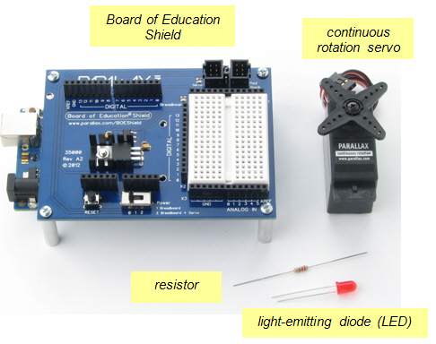
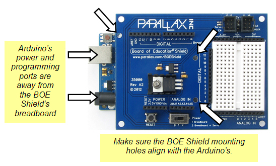
The Board of Education Shield makes it easy to build circuits and connect servos to the Arduino module. In this chapter, you will use it to test servos and indicator lights. Next chapter, you’ll mount the BOE Shield and servos on a robot chassis to build a robot we’ll call the BOE Shield-Bot.
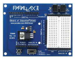
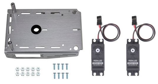
(1) Arduino module
(1) Board of Education Shield
(4) 1″ round aluminum standoffs
(4) pan head screws, 1/4″ 4-40
(3) 1/2″ round nylon spacers*
(3) nylon nuts, 4-40*
(3) pan head screws, 7/8″, 4-40*
(*Items also included in the Boe-Bot to Shield-Bot Retrofit Kit)
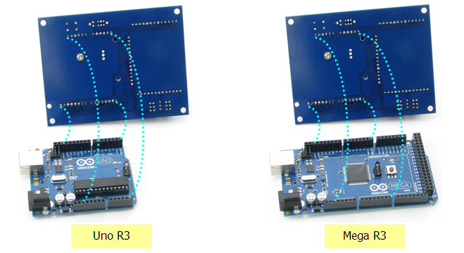
The four groups of pins under the Board of Education Shield plug into the four Arduino socket headers. There are also three board-connection holes in the shield that line up with holes in the Arduino module, designed to connect the two boards together with screws and nylon spacers.
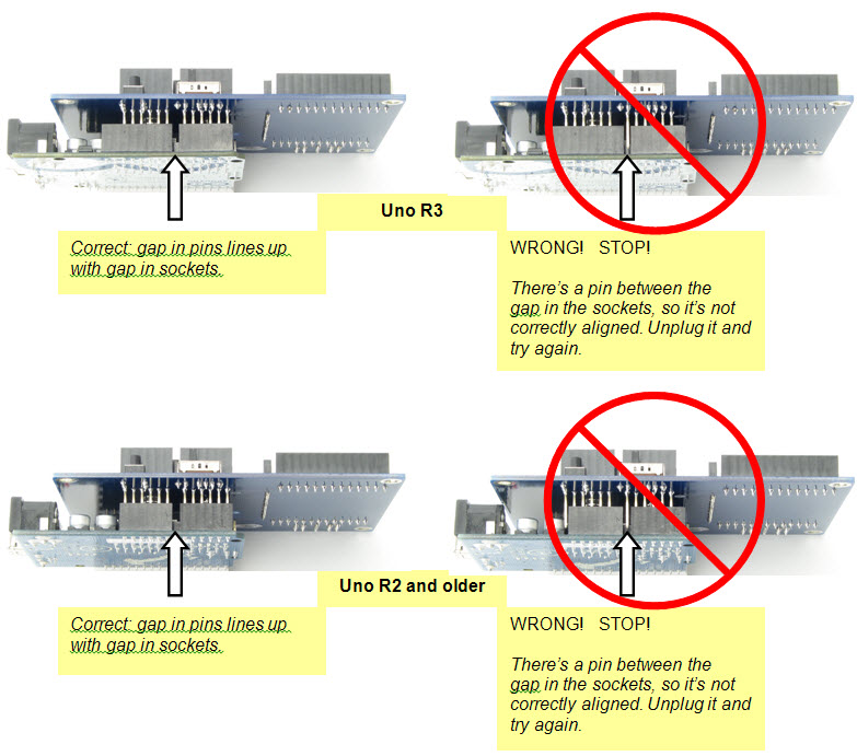
If you have a revision 3 Arduino, it will be labeled UNO R3 or MEGA R3 on the back. R3 boards will have two empty pairs of sockets, closest to the USB and power connectors, after socketing the shield. Earlier versions, such as 2, 1, and Duemilanove, have the same number of sockets as the shield has pins, so there will be no empty sockets left over. If you have an Arduino Mega, the four pin groups will fit into the four headers closest to the USB and power connectors, as shown in the box below.
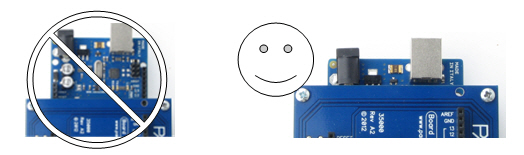
Component placement varies a little bit for the different Arduino models; some can only fit one or two nylon standoffs for holding the boards together. This is okay, but you need to find out which holes you can use before socketing the Board of Education Shield.
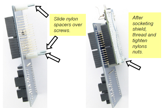
To keep the connected boards up off of the table, we’ll mount tabletop standoffs to each corner of the Board of Education Shield.
Indicator lights give people a way to see a representation of what’s going on inside a device, or patterns of communication between two devices. Next, you will build indicator lights to display the communication signals that the Arduino will send to the servos. If you haven’t ever built a circuit before, don’t worry, this activity shows you how.

A resistor is a component that resists the flow of electricity. This flow of electricity is called current. Each resistor has a value that tells how strongly it resists current flow. This resistance value is called the ohm, and the sign for the ohm is the Greek letter omega: Ω. (Later on you will see the symbol kΩ, meaning kilo-ohm, which is one thousand ohms.)
This resistor has two wires (called leads and pronounced “leeds”), one coming out of each end. The ceramic case between the two leads is the part that resists current flow. Most circuit diagrams use the jagged line symbol with a number label to indicate a resistor of a certain value, a 470 Ω resistor in this case. This is called a schematic symbol. The part drawing on the right is used in some beginner-level texts to help you identify the resistors in your kit, and where to place them when you build circuits.
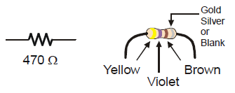
The resistors in your parts kit have colored stripes that indicate what their resistance values are. There is a different color combination for each resistance value. For example, the color code for the 470 Ω resistor is yellow-violet-brown.
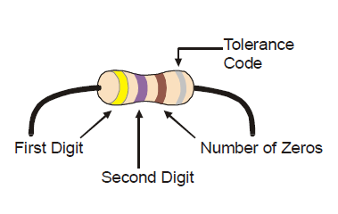
There may be a fourth stripe that indicates the resistor’s tolerance. Tolerance is measured in percent, and it tells how far off the part’s true resistance might be from the labeled resistance. The fourth stripe could be gold (5%), silver (10%) or no stripe (20%). For the activities in this book, a resistor’s tolerance does not matter, but its value does.
Each color bar on the resistor’s case corresponds to a digit, as listed in the table below.
| Digit | 0 | 1 | 2 | 3 | 4 | 5 | 6 | 7 | 8 | 9 |
| Color | black | brown | red | orange | yellow | green | blue | violet | gray | white |
Here’s how to find the resistor’s value, in this case proving that yellow-violet-brown is really 470 Ω:
Yellow-Violet-Brown = 4-7-0 = 470 Ω.
A diode is a one-way electric current valve, and a light-emitting diode (LED) emits light when current passes through it. Since an LED is a one-way current valve, you have to make sure to connect it the right way for it to work as intended.
An LED has two terminals: the anode and the cathode. The anode lead is labeled with the plus-sign (+) in the part drawing, and it is the wide part of the triangle in the schematic symbol. The cathode lead is the pin labeled with a minus-sign (-), and it is the line across the point of the triangle in the schematic symbol.
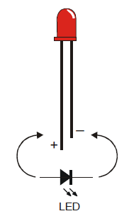
When you build an LED circuit, you will have to make sure the anode and cathode leads are connected to the circuit properly. You can tell them apart by the shape of the LED’s plastic case. Look closely at the case—it’s mostly round, but there is a small flat spot right near one of the leads, and that tells you it’s the cathode. Also note that the LED’s leads are different lengths. Usually, the shorter lead is connected to the cathode.
Always check the LED’s plastic case.
Usually, the longer lead is connected to the LED’s anode, and the shorter lead is connected to its cathode. But sometimes the leads have been clipped to the same length, or a manufacturer does not follow this convention. So, it’s best to always look for the flat spot on the case. If you plug an LED in backwards, it will not hurt it, but it won’t emit light until you plug it in the right way.
The white board with lots of square sockets in it is called a solderless breadboard. This breadboard has 17 rows of sockets. In each row, there are two five-socket groups separated by a trench in the middle. All the sockets in a 5-socket group are connected together underneath with a conductive metal clip. So, two wires plugged into the same 5‑socket group make electrical contact. This is how you will connect components, such as an LED and resistor, to build circuits. Two wires in the same row on opposite sides of the center trench will not be connected.
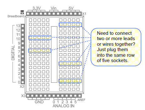
The prototyping area also has black sockets along the top, bottom, and left.
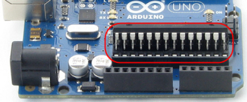
Digital and analog pins are the small pins on the Arduino module’s Atmel microcontroller chip. These pins electrically connect the microcontroller brain to the board.
A sketch can make the digital pins send high or low signals to circuits. In this chapter, we’ll do that to turn lights on and off. A sketch can also make a digital pin monitor high or low signals coming from a circuit; We’ll do that in another chapter to detect whether a contact switch has been pressed or released.
A sketch can also measure the voltages applied to analog pins; we’ll do that to measure light with a phototransistor circuit in another chapter.
(2) LEDs – Red
(2) Resistors, 220 Ω (red-red-brown)
(3) Jumper wires
Always disconnect power to your board before building or modifying circuits!
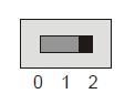
1. Set the BOE Shield’s Power switch to 0.
2. Disconnect the programming cable and battery pack.
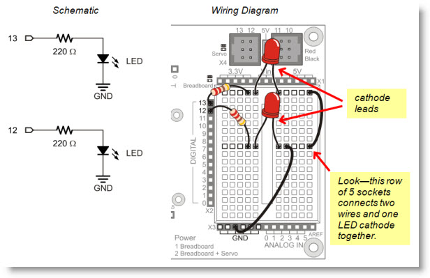
The image below shows the indicator LED circuit schematic on the left, and a wiring diagram example of the circuit built on your BOE Shield’s prototyping area on the right.
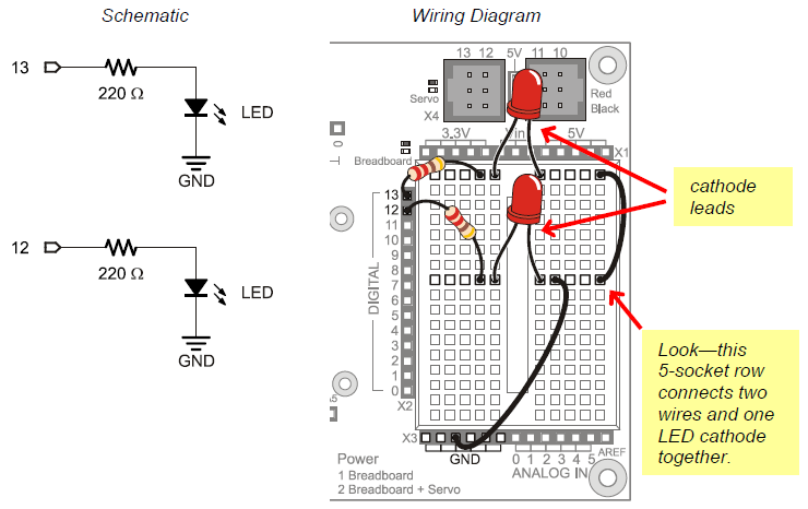
The next picture will give you an idea of what is going on when you program the Arduino to control the LED circuit. Imagine that you have a 5 volt (5 V) battery. The Board of Education Shield has a device called a voltage regulator that supplies 5 volts to the sockets labeled 5V. When you connect the anode end of the LED circuit to 5 V, it’s like connecting it to the positive terminal of a 5 V battery. When you connect the circuit to GND, it’s like connecting to the negative terminal of the 5 V battery.
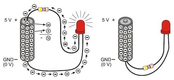
On the left side of the picture, one LED lead is connectd to 5 V and the other to GND. So, 5 V of electrical pressure causes electrons to flow through the circuit (electric current), and that current causes the LED to emit light. The circuit on the right side has both ends of the LED circuit connected to GND. This makes the voltage the same (0 V) at both ends of the circuit. No electrical pressure = no current = no light.
You can connect the LED to a digital I/O pin and program the Arduino to alternate the pin’s output voltage between 5 V and GND. This will turn the LED light on/off, and that’s what we’ll do next.
Volts is abbreviated V.
When you apply voltage to a circuit, it’s like applying electrical pressure. By convention, 5 V means “5 V higher than ground.” Ground, often abbreviated GND, is considered 0 V.
Ground is abbreviated GND.
The term ground originated with electrical systems where this connection is actually a metal rod that has been driven into the ground. In portable electronic devices, ground is commonly used to refer to connections that go to the battery supply’s negative terminal.
Current refers to the rate at which electrons pass through a circuit.
You will often see measurements of current expressed in amps, which is abbreviated A. The currents you will use here are measured in thousandths of an amp, or milliamps. For example, 10.3 mA passes through the circuit shown above.
Let’s start with a sketch that makes the LED circuit connected to digital pin 13 turn on/off. First, your sketch has to tell the Arduino to set the direction of pin 13 to output, using the pinMode function: pinMode(pin, mode). The pin parameter is the number of a digital I/O pin, and mode must be either INPUT or OUTPUT.
void setup()                      // Built-in initialization block
{
  pinMode(13, OUTPUT);            // Set digital pin 13 -> output
}
Now that digital pin 13 is set to output, we can use digitalWrite to turn the LED light on and off. Take a look at the picture below. On the left, digitalWrite(13, HIGH) makes the Arduino’s microcontroller connect digital pin 13 to 5 V, which turns on the LED. On the right, it shows how digitalWrite(13, LOW) makes it connect pin 13 to GND (0 V) to turn the LED off.

Here’s the loop function from the next sketch. First, digitalWrite(13, HIGH) turns the light on, delay(500) keeps it on for a half-second. Then digitalWrite(13, LOW) turns it off, and that’s also followed by delay(500). Since it’s inside the loop function’s block, the statements will repeat automatically. The result? The light will flash on/off once every second.
void loop()                        // Main loop auto-repeats
{
  digitalWrite(13, HIGH);          // Pin 13 = 5 V, LED emits light
  delay(500);                      // ..for 0.5 seconds
  digitalWrite(13, LOW);           // Pin 13 = 0 V, LED no light
  delay(500);                      // ..for 0.5 seconds
}
/*
 Robotics with the BOE Shield - HighLowLed
 Turn LED connected to digital pin 13 on/off once every second.
 */

void setup()                                 // Built-in initialization block
{
  pinMode(13, OUTPUT);                       // Set digital pin 13 -> output
}

void loop()                                  // Main loop auto-repeats
{
  digitalWrite(13, HIGH);                    // Pin 13 = 5 V, LED emits light
  delay(500);                                // ..for 0.5 seconds
  digitalWrite(13, LOW);                     // Pin 13 = 0 V, LED no light
  delay(500);                                // ..for 0.5 seconds
}
A timing diagram is a graph that relates a signal’s high and low stages to time. This timing diagram shows you a 1000 ms slice of the HIGH (5 V) and LOW (0 V) signals from the sketch HighLowLed. Can you see how delay(500) is controlling the blink rate?
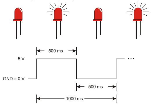
How would you make the LED blink twice as fast? How about reducing the delay function’s ms parameters by half?
Blinking the pin 12 LED is a simple matter of changing the pin parameter in the pinMode and two digitalWrite function calls.
You can also make both LEDs blink at the same time.
  pinMode(13, OUTPUT);         // Set digital pin 13 -> output
  pinMode(12, OUTPUT);         // Set digital pin 12 -> output
  digitalWrite(13, HIGH);      // Pin 13 = 5 V, LED emits light
  digitalWrite(12, HIGH);      // Pin 12 = 5 V, LED emits light
  delay(500);                  // ..for 0.5 seconds
  digitalWrite(13, LOW);       // Pin 13 = 0 V, LED no light
  digitalWrite(12, LOW);       // Pin 12 = 0 V, LED no light
  delay(500);                  // ..for 0.5 seconds
How would you modify the sketch again to turn one LED on while the other turns off? One circuit will need to receive a HIGH signal while the other receives a LOW signal.
The high and low signals that control servo motors must last for very precise periods of time. That’s because a servo motor measures how long the signal stays high, and uses that as an instruction for how fast, and in which direction, to turn its motor.
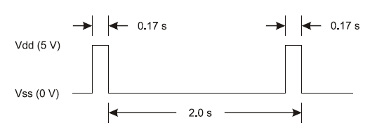
This timing diagram shows a servo signal that would make your Shield-Bot’s wheel turn full speed counterclockwise. There’s one big difference though: all the signals in this timing diagram last 100 times longer than they would if they were controlling a servo. This slows it down enough so that we can see what’s going on.
/*
    Robotics with the BOE Shield - ServoSlowMoCcw
    Send 1/100th speed servo signals for viewing with an LED.
 */

void setup()                                 // Built in initialization block
{
  pinMode(13, OUTPUT);                       // Set digital pin 13 -> output
}

void loop()                                  // Main loop auto-repeats
{
  digitalWrite(13, HIGH);                    // Pin 13 = 5 V, LED emits light
  delay(170);                                // ..for 0.17 seconds
  digitalWrite(13, LOW);                     // Pin 13 = 0 V, LED no light
  delay(1830);                               // ..for 1.83 seconds
}
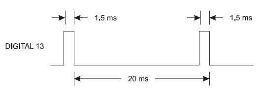
Alright, how about 1/10th speed instead of 1/100th speed?
Is the LED blinking 10 times faster now? Divide by 10 again for a full speed servo signal—we’ll have to round the numbers a bit:
Now you can see what the servo signal looks like with the indicator LED. The LED is flickering so fast, it’s just a glow. Since the high signal is 2 ms instead of 1.7 ms, it’ll be a little brighter than the actual servo control signal—the light is spending more time on. We could use this signal and programming technique to control a servo, but there’s an easier, more precise way. Let’s try it with LEDs first.
A better way to generate servo control signals is to include the Arduino Servo library in your sketch, one of the standard libraries of pre-written code bundled with the Arduino software.
We want to take a closer look at the Servo library.
attach()
writeMicroseconds()
detach()
Servos have to receive high-pulse control signals at regular intervals to keep turning. If the signal stops, so does the servo. Once your sketch uses the Servo library to set up the signal, it can move on to other code, like delays, checking sensors, etc. Meanwhile, the servo keeps turning because the Servo library keeps running in the background. It regularly interrupts the execution of other code to initiate those high pulses, doing it so quickly that it’s practically unnoticeable.
Using the Servo library to send servo control signals takes four steps:
#include <Servo.h> // Include servo library
Servo servoLeft; // Declare left servo
servoLeft.attach(13); // Attach left signal to pin 13
servoLeft.writeMicroseconds(1500); // 1.5 ms stay-still signal
Seconds, Milliseconds, Microseconds
A millisecond is a one-thousandth of a second, abbreviated ms.
A microsecond is a one-millionth of a second, abbreviated μs.
There are 1000 microseconds (μs) in 1 millisecond (ms).
There are 1,000,000 microseconds in 1 second (s).
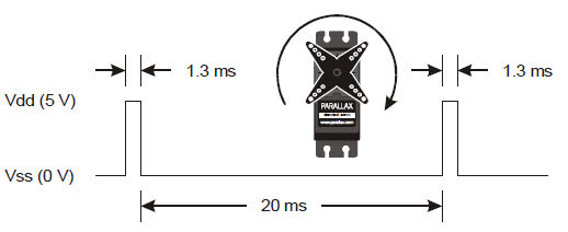
For calibrating servos, your sketch will need to send signals with 1.5 ms pulses. Take a look at the timing diagram below. This stay-still signal’s high pulses last 1.5 ms. That’s halfway between the 1.7 ms full-speed-counterclockwise and 1.3 ms full-speed-clockwise pulses.
/*
 Robotics with the BOE Shield – LeftServoStayStill
 Generate signal to make the servo stay still for centering.
 */

#include <Servo.h>                           // Include servo library

Servo servoLeft;                             // Declare left servo

void setup()                                 // Built in initialization block
{
  servoLeft.attach(13);                      // Attach left signal to pin 13
  servoLeft.writeMicroseconds(1500);         // 1.5 ms stay still signal
}

void loop()                                  // Main loop auto-repeats
{                                            // Empty, nothing needs repeating
}
You’ll be using this code a lot, so it’s a good idea to practice declaring an instance of Servo, attaching the signal to a pin, and setting the pulse duration.
Servo servoRight; // Declare right servo
servoRight.attach(12); // Attach right signal to pin 12
servoRight.writeMicroseconds(1500); // 1.5 ms stay still signal
/*
 Robotics with the BOE Shield – BothServosStayStill
 Generate signals to make the servos stay still for centering.
 */

#include <Servo.h>                           // Include servo library

Servo servoLeft;                             // Declare left servo signal
Servo servoRight;                            // Declare right servo signal

void setup()                                 // Built in initialization block
{
  servoLeft.attach(13);                      // Attach left signal to pin 13
  servoRight.attach(12);                      // Attach left signal to pin 12

  servoLeft.writeMicroseconds(1500);         // 1.5 ms stay still sig, pin 13
  servoRight.writeMicroseconds(1500);        // 1.5 ms stay still sig, pin 12
}

void loop()                                  // Main loop auto-repeats
{                                            // Empty, nothing needs repeating
}
From the robot navigation standpoint, continuous rotation servos offer a great combination of simplicity, usefulness and low price. The Parallax continuous rotation servos are the motors that will make the BOE Shield-Bot’s wheels turn, under Arduino control.
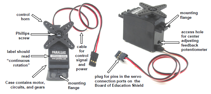
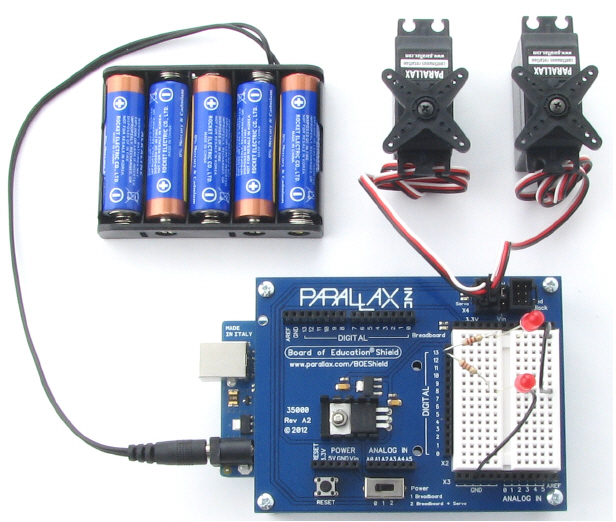
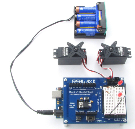
In this activity, you will connect your servos to the Board of Education Shield’s servo ports, which will connect them to supply voltage, ground, and a signal pin. You will also connect a battery supply to your Arduino because, under certain conditions, servos can end up demanding more current than a USB supply is designed to deliver.
Standard Servos vs. Continuous Rotation Servos
Standard servos are designed to receive electronic signals that tell them what position to hold. These servos control the positions of radio controlled airplane flaps, boat rudders, and car steering. Continuous rotation servos receive the same electronic signals, but instead turn at certain speeds and directions. Continuous rotation servos are handy for controlling wheels and pulleys.
Servo Control Horn, 4-point Star vs. Round
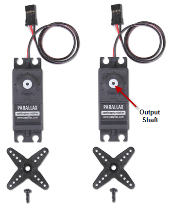
It doesn’t make a difference. So long as it is labeled “continuous rotation” it’s the servo for your BOE Shield-Bot. You’ll remove the control horn and replace it with a wheel.
Leave the LED circuits from the last activity on your board. They will be used later to monitor the signals the Arduino sends to the servos to control their motion.
(2) Parallax continuous rotation servos
BOE Shield with built and tested LED indicator circuits from the previous activity
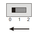
Between the servo headers on the BOE Shield is a jumper that connects the servo power supply to either Vin or 5V. To move it, pull it upwards and off the pair of pins it covers, then push it onto the pair of pins you want it to rest on. The BOE Shield-Bot’s battery pack will supply 7.5 V. Since the servos are rated for 4–6 V, we want to make sure the jumper is set to 5V. Also, a steady 5 V voltage supply will support a consistent servo speed, and more accurate navigation, than voltage that varies as batteries discharge.
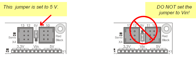
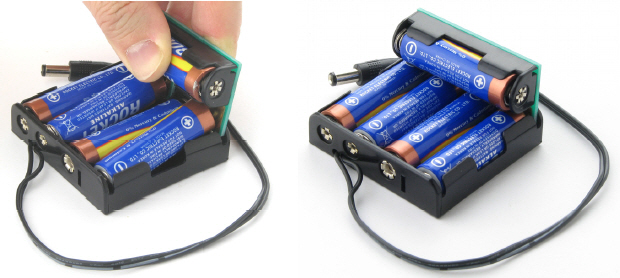
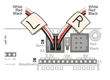
The picture below shows the schematic of the circuit you create by plugging the servos into ports 13 and 12 on the BOE Shield. Pay careful attention to wire color as you plug in the cables: the black wire should be at the bottom, and the white one should be at the top.
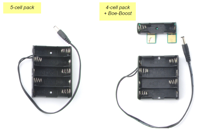
To properly power the servos, you’ll need to switch to an external battery pack now. When servos make sudden direction changes or push against resistance to rotation, they can draw more current than a USB port is designed to supply. Also, it would be no fun for the BOE Shield-Bot to be tethered to the computer forever! So, from here on out we’ll be using an external battery pack with five 1.5 V AA batteries. This will supply your system with 7.5 V and plenty of current for the voltage regulators and servos. From here forward, remember two things:
Rechargeable Options
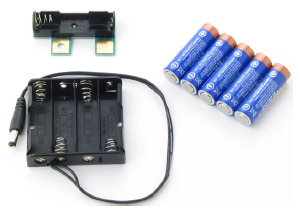
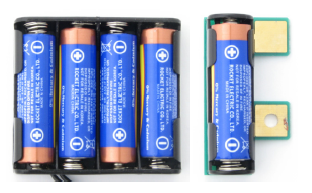
The thrifty Boe-Boost (#30078) allows you to add another cell in series with a 4-cell or 5-cell pack. Adding a 6th 1.2 V AA rechargeable cell to a 5-cell pack will supply 6 x 1.2 = 7.2 V.
The Li-ion Boe-Bot Power Pack-Charger (#28988) combines a lithium-ion battery pack and recharger in one board that you can mount under your Shield-Bot.
CAUTION: AC powered DC supplies are not recommended for the BOE Shield-Bot.
Some DC supplies provide much higher voltage than their rating. The BOE Shield-bot is designed for use with a 7.2–7.5 V battery supply. It will work with higher supply voltages at low loads, but the servo loads can heat up the regulator until it shuts off to protect itself.
(5) AA alkaline batteries
(1) 5-cell battery pack
(1) Boe-Boost
(1) 4-cell battery pack
(5) AA alkaline batteries

In this activity, you will run a sketch that sends the “stay-still” signal to the servos. You will then use a screwdriver to adjust the servos so that they actually stay still. This is called centering the servos. After the adjustment, you will run test sketches that will turn the servos clockwise and counterclockwise at various speeds.
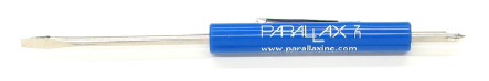
You’ll need a Phillips #1 point screwdriver with a 1/8″ (3.18 mm) or smaller shaft.
If a servo has not yet been centered, it may turn, vibrate, or make a humming noise when it receives the “stay-still” signal.
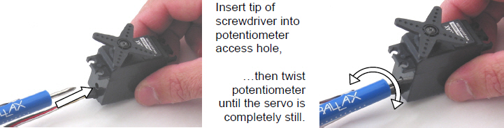
What’s a Potentiometer?
A potentiometer is kind of like an adjustable resistor with a moving part, such as a knob or a sliding bar, for setting the resistance. The Parallax continuous rotation servo’s potentiometer is a recessed knob that can be adjusted with a small Phillips screwdriver tip. Learn more about potentiometers in What’s a Microcontroller? and Basic Analog and Digital at www.parallax.com.
/*
 Robotics with the BOE Shield – RightServoStayStill
 Transmit the center or stay still signal on pin 12 for center adjustment.
 */

#include <Servo.h>                           // Include servo library

Servo servoRight;                            // Declare right servo

void setup()                                 // Built-in initialization block
{
  servoRight.attach(12);                     // Attach right signal to pin 12
  servoRight.writeMicroseconds(1500);        // 1.5 ms stay still signal
}

void loop()                                  // Main loop auto-repeats
{                                            // Empty, nothing needs repeating
}
There’s one last thing to do before assembling your BOE Shield-Bot, and that’s testing the servos. In this activity, you will run sketches that make the servos turn at different speeds and directions. This is an example of subsystem testing—a good habit to develop.
Subsystem testing is the practice of testing the individual components before they go into the larger device. It’s a valuable strategy that can help you win robotics contests. It’s also an essential skill used by engineers to develop everything from toys, cars, and video games to space shuttles and Mars roving robots. Especially in more complex devices, it can become nearly impossible to figure out a problem if the individual components haven’t been tested beforehand. In aerospace projects, for example, disassembling a prototype to fix a problem can cost hundreds of thousands, or even millions, of dollars. In those kinds of projects, subsystem testing is rigorous and thorough.
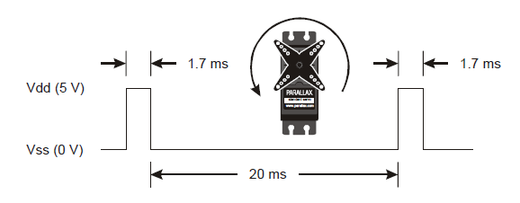
This timing diagram shows how a Parallax continuous rotation servo turns full speed clockwise when you send it 1.3 ms pulses. Full speed typically falls in the 50 to 60 RPM range.
What’s RPM? Revolutions Per Minute—the number of full rotations turned in one minute.
What’s a pulse train? Just as a railroad train is a series of cars, a pulse train is a series of pulses (brief high signals).
/*
 Robotics with the BOE Shield – LeftServoClockwise
 Generate a servo full speed clockwise signal on digital pin 13.
 */

#include <Servo.h>                           // Include servo library

Servo servoLeft;                             // Declare left servo

void setup()                                 // Built in initialization block
{
  servoLeft.attach(13);                      // Attach left signal to pin 13
  servoLeft.writeMicroseconds(1300);         // 1.3 ms full speed clockwise
}

void loop()                                  // Main loop auto-repeats
{                                            // Empty, nothing needs repeating
}
/*
 Robotics with the BOE Shield – RightServoClockwise
 Generate a servo full speed clockwise signal on digital pin 12.
 */

#include <Servo.h>                           // Include servo library

Servo servoRight;                            // Declare left servo

void setup()                                 // Built in initialization block
{
  servoRight.attach(12);                     // Attach left signal to pin 12
  servoRight.writeMicroseconds(1300);        // 1.3 ms full speed clockwise
}

void loop()                                  // Main loop auto-repeats
{                                            // Empty, nothing needs repeating
}
For BOE Shield-Bot navigation, we need to control both servos at once.
 /*
 Robotics with the BOE Shield – ServosOppositeDirections
 Generate a servo full speed counterclockwise signal with pin 13 and
 full speed clockwise signal with pin 12.
 */

#include <Servo.h>                           // Include servo library

Servo servoLeft;                             // Declare left servo signal
Servo servoRight;                            // Declare right servo signal

void setup()                                 // Built in initialization block
{
  servoLeft.attach(13);                      // Attach left signal to pin 13
  servoRight.attach(12);                     // Attach right signal to pin 12

  servoLeft.writeMicroseconds(1700);         // 1.7 ms -> counterclockwise
  servoRight.writeMicroseconds(1300);        // 1.3 ms -> clockwise
}

void loop()                                  // Main loop auto-repeats
{                                            // Empty, nothing needs repeating
}
This opposite-direction control will be important soon. Think about it: when the servos are mounted on either side of a chassis, one will have to rotate clockwise while the other rotates counterclockwise to make the BOE Shield-Bot roll in a straight line. Does that seem odd? If you can’t picture it, try this:
Pulse Width Modulation
Adjusting the property of a signal to carry information is called modulation. We’ve discovered that servo control signals are a series of high pulses separated by low resting states. How long the high pulse lasts—how wide the high pulse looks in a timing diagram—determines the speed and direction that the servo turns. That adjustable pulse width carries the servo setting information. Therefore, we can say that servos are controlled with pulse width modulation.
Different combinations of writeMicroseconds us parameters will be used repeatedly for programming your BOE Shield-Bot’s motion. By testing several possible combinations and filling in the Description column of Table 2‑2, you will become familiar with them and build a reference for yourself. You’ll fill in the Behavior column later on, when you see how the combinations make your assembled BOE Shield-Bot move.

It’s easy to control how long the servos run when using the Servo library. Once set, a servo will maintain its motion until it receives a new setting. So, to make a servo run for a certain length of time, all you have to do is insert a delay after each setting.
/*
 Robotics with the BOE Shield – ServoRunTimes
 Generate a servo full speed counterclockwise signal with pin 13 and
 full speed clockwise signal with pin 12.
 */

#include <Servo.h>                           // Include servo library

Servo servoLeft;                             // Declare left servo signal
Servo servoRight;                            // Declare right servo signal

void setup()                                 // Built in initialization block
{
  servoLeft.attach(13);                      // Attach left signal to pin 13
  servoRight.attach(12);                     // Attach right signal to pin 12

  servoLeft.writeMicroseconds(1300);         // Pin 13 clockwise
  servoRight.writeMicroseconds(1300);        // Pin 12 clockwise
  delay(3000);                               // ..for 3 seconds
  servoLeft.writeMicroseconds(1700);         // Pin 13 counterclockwise
  servoRight.writeMicroseconds(1700);        // Pin 12 counterclockwise
  delay(3000);                               // ..for 3 seconds
  servoLeft.writeMicroseconds(1500);         // Pin 13 stay still
  servoRight.writeMicroseconds(1500);        // Pin 12 stay still
}

void loop()                                  // Main loop auto-repeats
{                                            // Empty, nothing needs repeating
}
The focus of this chapter was calibrating and testing the servos, and building indicator lights to monitor the servo signals. In addition to some hardware setup, many concepts related to electronics, programming, and even a few good engineering concepts were introduced along the way.
Hardware Setup
Electronics
Programming
Engineering
Question Solutions
digitalWrite(13, HIGH) // 5 V
digitalWrite(13, LOW)  // 0 V
Exercise Solutions
void loop()                    // Main loop auto-repeats
{                              // 200 ms -> 5 blinks/second
  digitalWrite(13, HIGH);      // Pin 13 = 5 V, LED emits light
  delay(50);                   // ..for 0.05 seconds
  digitalWrite(13, LOW);       // Pin 13 = 0 V, LED no light
  delay(150);                  // ..for 0.15 seconds
}
void setup()                   // Built in initialization block
{
  servoLeft.attach(13);        // Attach left signal to pin 13
  servoRight.attach(12);       // Attach right signal to pin 12

  servoLeft.writeMicroseconds(1300);  // 1.3 ms -> clockwise
  servoRight.writeMicroseconds(1500); // 1.5 ms -> stop
  delay(1200);                        // ..for 1.2 seconds
  servoLeft.writeMicroseconds(1500);  // 1.5 ms -> stop
}
void setup()                   // Built in initialization block
{
  servoLeft.attach(13);        // Attach left signal to pin 13
  servoRight.attach(12);       // Attach right signal to pin 12

  servoLeft.writeMicroseconds(1700);  // 1.7 ms -> cc-wise
  servoRight.writeMicroseconds(1300); // 1.3 ms -> clockwise
  delay(1500);                        // ..for 1.5 seconds
  servoRight.writeMicroseconds(1700); // 1.7 ms -> cc-wise
  delay(1500);
  servoLeft.writeMicroseconds(1500);  // 1.5 ms -> stop
  servoRight.writeMicroseconds(1500); // 1.5 ms -> stop
}
Project Solutions
/*
 Robotics with the BOE Shield – Chapter 2, Project 1
 Generate a servo full speed counterclockwise signal with pin 13 and
 full speed clockwise signal with pin 12.
 */

#include <Servo.h>                    // Include servo library

Servo servoLeft;                      // Declare left servo signal
Servo servoRight;                     // Declare right servo signal

void setup()                          // Built in initialization block
{
  servoLeft.attach(13);               // Attach left signal to pin 13
  servoRight.attach(12);              // Attach right signal to pin 12

  servoLeft.writeMicroseconds(1700);  // Pin 13 counterclockwise
  servoRight.writeMicroseconds(1300); // Pin 12 clockwise
  delay(3000);                        // ..for 3 seconds
  servoLeft.detach();                 // Stop servo signal to pin 13
  servoRight.detach();                // Stop servo signal to pin 12
}

void loop()                           // Main loop auto-repeats
{                                     // Empty, nothing needs repeating
}
This chapter contains instructions for building and testing your BOE Shield-Bot. It’s especially important to complete the testing portion before moving on to the next chapter. By doing so, you can help avoid a number of common mistakes that could otherwise lead to mystifying BOE Shield-Bot behavior. Here is a summary of what you will do:
Code Update Notice
The Chapter 3 Arduino Code was updated on 11/15/2012. See the notice on this page for details.
This activity will guide you through assembling the BOE Shield-Bot, step by step. In each step, you will gather a few of the parts, and then assemble them so that they match the pictures. Each picture has instructions that go with it; make sure to follow them carefully.
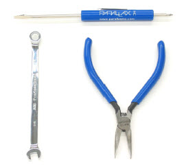
All of the tools needed are common and can be found in most households and school shops. They can also be purchased at local hardware stores. The Parallax screwdriver is included in the Robotics Shield Kit, and the other two are optional but handy to have.
Note: It is completely normal to have some hardware left over after assembly. The hardware pack includes everything you need to build your robot plus extras of the most commonly lost parts.
(1) screwdriver, Phillips #1
(1) 1/4″ combination wrench (optional but handy)
(1) needle-nose pliers (optional)
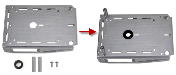
(1) robot chassis
(2) 1″ standoffs (removed from BOE Shield)
(2) pan-head screws, 1/4″ 4-40 (removed from BOE Shield)
(1) rubber grommet, 13/32″
(2) Parallax continuous rotation servos, previously centered
STOP! Before taking the next step, you must have completed these activities: Chapter 2, Activity 4: Connect Servo Motors and Batteries, and Chapter 2, Activity 5: Centering the Servos.
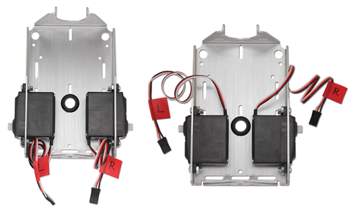
BOE Shield-Bot Chassis, partially assembled.
(2) Parallax continuous rotation servos
(8) pan Head Screws, 3/8″ 4-40
(8) nuts, 4-40 or lock nuts
1/4″ combination wrench (optional, needed for locknuts only)
masking tape
pen
Note: You can choose to use either hex nuts or locknuts to mount your servos, both are provided. Locknuts provide a tighter connection, but if your robots need frequent repair or part replacements then hex nuts are the easiest to remove and reattach quickly.
(2) Nylon flat-head slotted screws, 3/8″ 4-40
(2) 1″ standoffs (removed from BOE Shield previously)
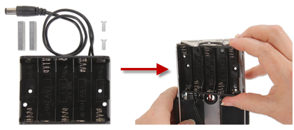
(1) 5-cell battery pack with 2.1 mm center-positive plug
(1) 1/16″ cotter pin
(1) tail wheel ball
(2) O-ring tires
(2) plastic machined wheels
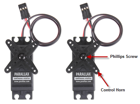
(2) screws saved when removing the servo horns
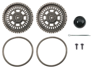
The robot’s tail wheel is merely a plastic ball with a hole through the center. A cotter pin holds it to the chassis and functions as an axle for the wheel.
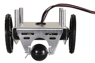
When you are done, your completed chassis will look like one of the pictures below.
Left: “Outside-forward” servos
Right: “Inside-backward” servos
(4) pan-head screws, 1/4″ 4-40
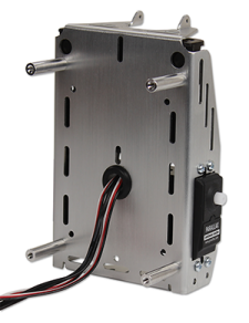
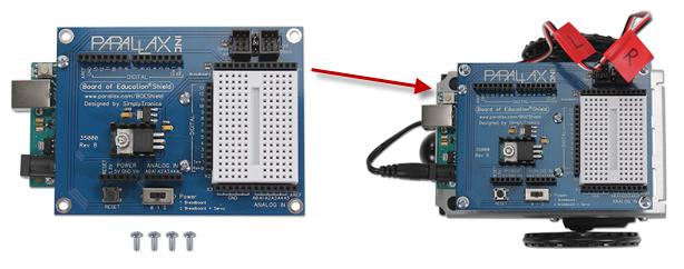
(1) Board of Education Shield mounted to your Arduino module and secured with standoffs.
Using Different Pins for the Servos
The Arduino toggles Pin 13 briefly upon startup or reset. If this causes problems for a particular application, you can use Pins 11 and 12 instead of 12 and 13. Be sure to adjust your code accordingly.
If you are building the BOE Shield-Bot to use with ROBOTC instead of for this tutorial, follow these instructions for using different servo ports.
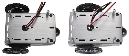
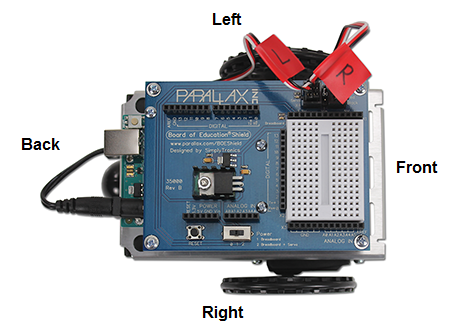
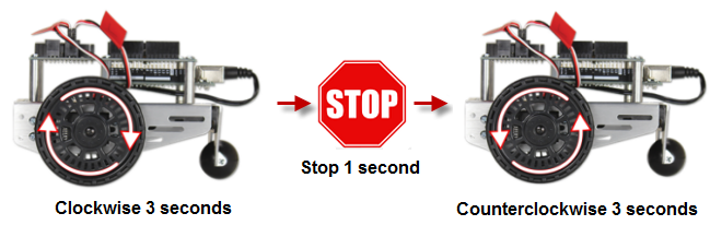
In this activity, you will test to make sure that the electrical connections between your board and the servos are correct. The picture below shows your BOE Shield-Bot’s front, back, left, and right. We need to make sure that the right-side servo turns when it receives pulses from pin 12 and that the left-side servo turns when it receives pulses from pin 13.
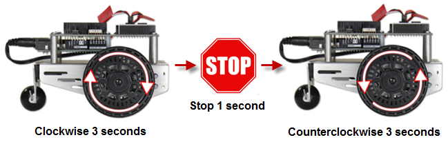
The next example sketch will test the servo connected to the right wheel, shown below. The sketch will make this wheel turn clockwise for three seconds, then stop for one second, then turn counterclockwise for three seconds.
/*
 * Robotics with the BOE Shield - RightServoTest
 * Right servo turns clockwise three seconds, stops 1 second, then
 * counterclockwise three seconds.
 */

#include <Servo.h>                           // Include servo library

Servo servoRight;                            // Declare right servo

void setup()                                 // Built in initialization block
{
  servoRight.attach(12);                     // Attach right signal to pin 12

  servoRight.writeMicroseconds(1300);        // Right wheel clockwise
  delay(3000);                               // ...for 3 seconds

  servoRight.writeMicroseconds(1500);        // Stay still
  delay(1000);                               // ...for 3 seconds

  servoRight.writeMicroseconds(1700);        // Right wheel counterclockwise
  delay(3000);                               // ...for 3 seconds

  servoRight.writeMicroseconds(1500);        // Right wheel counterclockwise

}

void loop()                                  // Main loop auto-repeats
{                                            // Empty, nothing needs repeating
}
Now, it’s time to run the same test on the left wheel as shown below. This involves modifying the RightServoTest sketch.
Here is a list of some common symptoms and how to fix them.
The first step is to double check your sketch and make sure all the code is correct.
The servo doesn’t turn at all.
The left servo turns when the right one is supposed to.
This means that the servos are swapped. The servo that’s connected to pin 12 should be connected to pin 13, and the servo that’s connected to pin 13 should be connected to pin 12.
The wheel does not fully stop; it still turns slowly.
If the wheel keeps turning slowly after the clockwise, stop, counterclockwise sequence, it means that the servo may not be exactly centered. There are two ways to fix this:
The wheel never stops, it just keeps turning rapidly.
If you are sure the code in your sketch is correct, it probably means your servo is not properly centered.
In this activity, we’ll build a small noise-making circuit on the BOE Shield’s prototyping area that will generate a tone if the robot’s batteries run too low.
When the voltage supply drops below the level a device needs to function properly, it’s called brownout. The device (your Arduino) typically shuts down until the supply voltage returns to normal. Then, it will restart whatever sketch it was running.
Brownouts typically happen when batteries are already running low, and the servos suddenly demand more power. For example, if the BOE Shield-Bot changes from full speed forward to full speed backward, the servos have to do extra work to stop the servos and then go the other direction. For this, they need more current, and when they try to pull that current from tired batteries, the output voltage dips enough to cause brownout.
Now, imagine your BOE Shield-Bot is navigating through a routine, and suddenly it stops for a moment and then goes in a completely unexpected direction. How will you know if it is a mistake in your code, or if it’s a brownout? One simple, effective solution is to add a speaker to your BOE Shield-Bot and make it play a “start” tone at the beginning of every sketch. That way, if your BOE Shield-Bot has a brownout while it’s navigating, you’ll know right away because it’ll play the start tone.
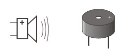
We’ll use a device called a piezoelectric speaker (piezospeaker) that can make different tones depending on the frequency of high/low signals it receives from the Arduino. The schematic symbol and part drawing are shown below.
Frequency is the measurement of how often something occurs in a given amount of time.
A piezoelectric element is a crystal that changes shape slightly when voltage is applied to it. Applying high and low voltages at a rapid rate causes the crystal to rapidly change shape. The resulting vibration in turn vibrates the air around it, and this is what our ear detects as a tone. Every rate of vibration makes a different tone.
Piezoelectric elements have many uses. When force is applied to a piezoelectric element, it can create voltage. Some piezoelectric elements have a frequency at which they naturally vibrate. These can be used to create voltages at frequencies that function as the clock oscillator for many computers and microcontrollers.
(1) piezospeaker (just peel off the “Remove the seal after washing” sticker if it has one)
(misc.) jumper wires
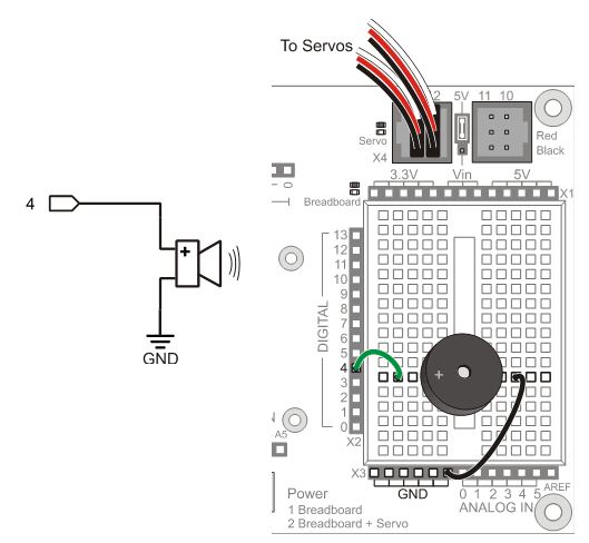
The picture below shows a wiring diagram for adding a piezospeaker to the breadboard.
Always disconnect power before building or modifying circuits!
Set the Power switch to 0.
Unplug the battery pack.
Unplug the programming cable.
The next example sketch tests the piezospeaker using calls to the Arduino’s tone function. True to its name, this function send signals to speakers to make them play tones.
There are two options for calling the tone function. One allows you to specify the pin and frequency (pitch) of the tone. The other allows you to specify pin, frequency, and duration (in milliseconds). We’ll be using the second option since we don’t need the tone to go on indefinitely.
tone(pin, frequency) tone(pin, frequency, duration)
This piezospeaker is designed to play 4.5 kHz tones for smoke alarms, but it can also play a variety of audible tones and usually sounds best in the 1 kHz to 3.5 kHz range. The start-alert tone we’ll use is:
tone(4, 3000, 1000);
delay(1000);
That will make pin 4 send a series of high/low signals repeating at 3 kHz (3000 times per second). The tone will last for 1000 ms, which is 1 second. The tone function continues in the background while the sketch moves on to the next command. We don’t want the servos to start moving until the tone is done playing, so the tone command is followed by delay(1000) to let the tone finish before the sketch can move on to servo control.
Frequency can be measured in hertz (Hz) which is the number of times a signal repeats itself in one second. The human ear is able to detect frequencies in a range from very low pitch (20 Hz) to very high pitch (20 kHz or 20,000 Hz). One kilohertz is one-thousand-times-per-second, abbreviated 1 kHz.
This example sketch makes a beep when it starts running, then it goes on to send Serial Monitor messages every half-second. These messages will continue indefinitely because they are in the loop function. If the power to the Arduino is interrupted, the sketch will start at the beginning again, and you will hear the beep.
/*
 * Robotics with the BOE Shield - StartResetIndicator
 * Test the piezospeaker circuit.
 */

void setup()                                 // Built in initialization block
{
  Serial.begin(9600);
  Serial.println("Beep!");

  tone(4, 3000, 1000);                       // Play tone for 1 second
  delay(1000);                               // Delay to finish tone
}

void loop()                                  // Main loop auto-repeats
{
  Serial.println("Waiting for reset...");
  delay(1000);
}
StartResetIndicator begins by displaying the message “Beep!” in the Serial Monitor. Then, immediately after printing the message, the tone function plays a 3 kHz tone on the piezoelectric speaker for 1 second. Because the instructions are executed so rapidly by the Arduino, it should seem as though the message is displayed at the same instant the piezospeaker starts to play the tone.
When the tone is done, the sketch enters the loop function, which displays the same “Waiting for reset…” message over and over again. Each time the reset button on the BOE Shield is pressed or the power is disconnected and reconnected, the sketch starts over again with the “Beep!” message and the 3 kHz tone.
Sketch Update Notice!!!
The sketch StartResetIndicator was updated on 11/16/2012. On the Arduino Mega 2650, the upload hangs with the original code listing. The offending command was:
Serial.println(“Beep!!!”);
It turns out that having more than one exclamation point in a row in a serial string causes this problem in the Mega 2650. From this point forward, we will find another way to express our enthusiasm in serial strings. – Editor.
We’ll use tone at the beginning of every example sketch from here onward. So, it’s a good idea to get in the habit of putting tone and delay statements at the beginning of every sketch’s setup function.
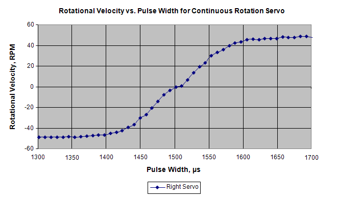
This graph shows pulse time vs. servo speed. The graph’s horizontal axis shows the pulse width in microseconds (µs), and the vertical axis shows the servo’s response in RPM. Clockwise rotation is shown as negative, and counterclockwise is positive. This particular servo’s graph, which can also be called a transfer curve, ranges from about -48 to +48 RPM over the range of test pulse widths from 1300 to 1700 µs. A transfer curve graph of your servos would be similar.
With this sketch, you can check servo RPM speed (and direction) for pulse values from 1375 µs to 1625 µs in steps of 25 μs. These speed measurements will help make it clear how servo control pulse durations in the 1400 to 1600 µs range control servo speed. This sketch starts by displaying the pulse duration that it’s ready to send as a servo control signal. Then, it waits for you to send the Arduino a character with the Serial Monitor before it runs the servo. It runs the servo for six seconds, and during that time you can count the number of full turns the wheel makes. After that, the for loop repeats itself, and increases the pulse duration by 25 for the next test.
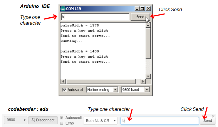
/*
 Robotics with the BOE Shield – TestServoSpeed
 Send a character from the Serial Monitor to the Arduino to make it run the
 left servo for 6 seconds.  Starts with 1375 us pulses and increases by
 25 us with each repetition, up to 1625 us.  This sketch is useful for
 graphing speed vs. pulse width.
 */

#include <Servo.h>                           // Include servo library

Servo servoLeft;                             // Declare left servo signal
Servo servoRight;                            // Declare right servo signal

void setup()                                 // Built in initialization block
{
  tone(4, 3000, 1000);                       // Play tone for 1 second
  delay(1000);                               // Delay to finish tone

  Serial.begin(9600);                        // Set data rate to 9600 bps
  servoLeft.attach(13);                      // Attach left signal to P13
}

void loop()                                  // Main loop auto-repeats
{

  // Loop counts with pulseWidth from 1375 to 1625 in increments of 25.

  for(int pulseWidth = 1375; pulseWidth <= 1625; pulseWidth += 25)
  {
    Serial.print("pulseWidth = ");           // Display pulseWidth value
    Serial.println(pulseWidth);
    Serial.println("Press a key and click"); // User prompt
    Serial.println("Send to start servo...");

    while(Serial.available() == 0);          // Wait for character
    Serial.read();                           // Clear character

    Serial.println("Running...");
    servoLeft.writeMicroseconds(pulseWidth); // Pin 13 servo speed = pulse
    delay(6000);                             // ..for 6 seconds
    servoLeft.writeMicroseconds(1500);       // Pin 13 servo speed = stop
  }
}
The sketch TestServoSpeed increments the value of a variable named pulseWidth by 25 each time through a for loop.
  // Loop counts with pulseWidth from 1375 to 1625 in increments of 25.

  for(int pulseWidth = 1375; pulseWidth <= 1625; pulseWidth += 25)
With each repetition of the for loop, it displays the value of the next pulse width that it will send to the pin 13 servo, along with a user prompt.
    Serial.print("pulseWidth = ");           // Display pulseWidth value
    Serial.println(pulseWidth);
    Serial.println("Press a key and click"); // User prompt
    Serial.println("Send to start servo...");
After Serial.begin in the setup loop, the Arduino sets aside some memory for characters coming in from the Serial Monitor. This memory is typically called a serial buffer, and that’s where ASCII values from the Serial Monitor are stored. Each time you use Serial.read to get a character from the buffer, the Arduino subtracts 1 from the number of characters waiting in the buffer.
A call to Serial.available will tell you how many characters are in the buffer. This sketch uses while(Serial.available() = = 0) to wait until the Serial Monitor sends a character. Before moving on to run the servos, it uses Serial.read( ) to remove the character from the buffer. The sketch could have used int myVar = Serial.read( ) to copy the character to a variable. Since the code isn’t using the character’s value to make decisions, it just calls Serial.read, but doesn’t copy the result anywhere. The important part is that it needs to clear the buffer so that Serial.available( ) returns zero next time through the loop.
while(Serial.available() == 0);      // Wait for character
Serial.read();                       // Clear character
Where is the while loop’s code block?
The C language allows the while loop to use an empty code block, in this case to wait there until it receives a character. When you type a character into the Serial Monitor, Serial.available returns 1 instead of 0, so the while loop lets the sketch move on to the next statement. Serial.read removes that character you typed from the Arduino’s serial buffer to make sure that Serial.available returns 0 next time through the loop. You could have typed this empty while loop other ways:
while(Serial.available() == 0) {}
…or:
while(Serial.available() == 0) {}; .
After the Arduino receives a character from the keyboard, it displays the “Running…” message and then makes the servo turn for 6 seconds. Remember that the for loop this code is in starts the pulseWidth variable at 1375 and adds 25 to it with each repetition. So, the first time through the loop, servoLeft is 1375, the second time through it’s 1400, and so on all the way up to 1625.
Each time through the loop, servoLeft.writeMicroseconds(pulseWidth) uses the value that pulseWidth stores to set servo speed. That’s how it updates the servo’s speed each time you send a character to the Arduino with the Serial Monitor.
Serial.println("Running...");
servoLeft.writeMicroseconds(pulseWidth); // Pin 13 speed=pulse
delay(6000);                             // ..for 6 seconds
servoLeft.writeMicroseconds(1500);       // Pin 13 speed=stop
You can use the table below to record the data for your own transfer curve. The TestServoSpeed sketch’s loop can be modified to test every value in the table, or every other value to save time.
for(int pulseWidth=1375; pulseWidth <= 1625; pulseWidth += 25)
…to:
for(int pulseWidth=1300; pulseWidth <= 1700; pulseWidth += 20)
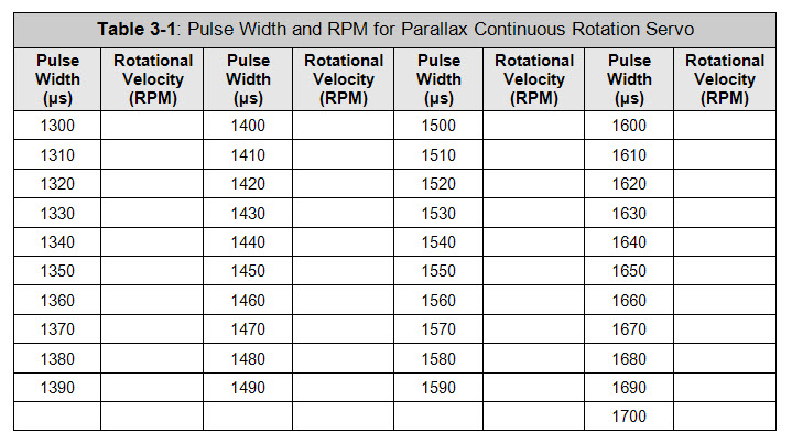
This chapter covered BOE Shield-Bot assembly and testing. Assembly involved both mechanical construction and circuit-building, and testing used some new programming concepts. Here are the highlights:
Hardware Setup
Electronics
Programming
Engineering Skills
/*
 Robotics with the BOE Shield – Chapter 3, Project 1
*/

#include <Servo.h>                           // Include servo library

Servo servoLeft;                             // Declare left servo signal
Servo servoRight;                            // Declare right servo signal

void setup()                                 // Built in initialization block
{
  tone(4, 3000, 1000);                       // Play tone for 1 second
  delay(1000);                               // Delay to finish tone

  Serial.begin(9600);                        // Set data rate to 9600 bps
  servoLeft.attach(13);                      // Attach left signal to P13
}

void loop()                                  // Main loop auto-repeats
{

  // Loop counts with pulseWidth from 1375 to 1625 in increments of 25.

  for(int pulseWidth = 1375; pulseWidth <= 1625; pulseWidth += 25)
  {
    Serial.print("pulseWidth = ");           // Display pulseWidth value
    Serial.println(pulseWidth);
    Serial.println("Press a key and click"); // User prompt
    Serial.println("Send to start servo...");

    while(Serial.available() == 0);          // Wait for character
    Serial.read();                           // Clear character

    Serial.println("Running...");
    servoLeft.writeMicroseconds(pulseWidth);   // Pin 13 servo speed = pulse
    delay(6000);                               // ..for 6 seconds
    servoLeft.writeMicroseconds(1500);         // Pin 13 servo speed = stop
    tone(4, 4000, 75);                         // Test complete
  }
}
servoRight.writeMicroseconds(1500 + (1500 – pulseWidth))
Remember to add a servoRight.writeMicroseconds(1500) after the 6-second run time.
/*
 Robotics with the BOE Shield – Chapter 3, Project 2
*/

#include <Servo.h>                           // Include servo library

Servo servoLeft;                             // Declare left servo signal
Servo servoRight;                            // Declare right servo signal

void setup()                                 // Built in initialization block
{
  tone(4, 3000, 1000);                       // Play tone for 1 second
  delay(1000);                               // Delay to finish tone

  Serial.begin(9600);                        // Set data rate to 9600 bps
  servoLeft.attach(13);                      // Attach left signal to P13
  servoRight.attach(12);                     // Attach right signal to P12
}

void loop()                                  // Main loop auto-repeats
{

  // Loop counts with pulseWidth from 1375 to 1625 in increments of 25.

  for(int pulseWidth = 1375; pulseWidth <= 1625; pulseWidth += 25)
  {
    Serial.print("pulseWidth = ");           // Display pulseWidth value
    Serial.println(pulseWidth);
    Serial.println("Press a key and click"); // User prompt
    Serial.println("Send to start servo...");

    while(Serial.available() == 0);          // Wait for character
    Serial.read();                           // Clear character

    Serial.println("Running...");
    servoLeft.writeMicroseconds(pulseWidth);   // Pin 13 servo speed = pulse
    // Pin 12 servo opposite direction of pin 13 servo.
    servoRight.writeMicroseconds(1500 + (1500 - pulseWidth));
    delay(6000);                               // ..for 6 seconds
    servoLeft.writeMicroseconds(1500);         // Pin 13 servo speed = stop
    servoRight.writeMicroseconds(1500);        // Pin 12 servo speed = stop
    tone(4, 4000, 75);                         // Test complete
  }
}
This chapter introduces different programming strategies to make the BOE Shield-Bot move. Once we understand how basic navigation works, we’ll make functions for each maneuver. In later chapters, we’ll write sketches that call these functions in response to sensor input, which will allow the BOE Shield-Bot to navigate on its own.
The first step is to get oriented! The picture below shows forward, backward, left turn, and right turn from the point of view of the BOE Shield-Bot.
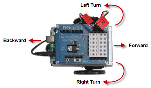
Here are the goals of this chapter’s activities:
Have you ever thought about what direction a car’s wheels have to turn to propel it forward? The wheels turn opposite directions on opposite sides of the car. Likewise, to make the BOE Shield-Bot go forward, its left wheel has to turn counterclockwise, but its right wheel has to turn clockwise.
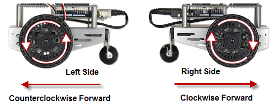
Remember that a sketch can use the Servo library’s writeMicroseconds function to control the speed and direction of each servo. Then, it can use the delay function to keep the servos running for certain amounts of time before choosing new speeds and directions. Here’s an example that will make the BOE Shield-Bot roll forward for about three seconds, and then stop.
// Robotics with the BOE Shield - ForwardThreeSeconds
// Make the BOE Shield-Bot roll forward for three seconds, then stop.

#include <Servo.h>                           // Include servo library

Servo servoLeft;                             // Declare left and right servos
Servo servoRight;

void setup()                                 // Built-in initialization block
{
  tone(4, 3000, 1000);                       // Play tone for 1 second
  delay(1000);                               // Delay to finish tone

  servoLeft.attach(13);                      // Attach left signal to pin 13
  servoRight.attach(12);                     // Attach right signal to pin 12

  // Full speed forward
  servoLeft.writeMicroseconds(1700);         // Left wheel counterclockwise
  servoRight.writeMicroseconds(1300);        // Right wheel clockwise
  delay(3000);                               // ...for 3 seconds

  servoLeft.detach();                        // Stop sending servo signals
  servoRight.detach();
}

void loop()                                  // Main loop auto-repeats
{                                            // Empty, nothing needs repeating
}
First, the Servo library has to be included so that your sketch can access its functions:
#include <Servo.h> // Include servo library
Next, an instance of Servo must be declared and uniquely named for each wheel:
  Servo servoLeft;                     // Declare left & right servos
  Servo servoRight;
Instance of an Object
An object is a block of pre-written code that can be copied and re-used multiple times in a single sketch. Each copy, called an object instance, can be configured differently. For example, the two Servo declarations create two instances of the object’s code, named servoLeft and servoRight. Then, functions within each instance can be called and configured individually. So, servoLeft.attach(13) configures the servoLeft object instance to send its servo control signals to pin 13. Likewise, servoRight.attach(12) tells the servoRight object instance to send its signals to pin 12.
A sketch automatically starts in its setup function. It runs the code in there once before moving on to the loop function, which automatically keeps repeating. Since we only want the BOE Shield-Bot to go forward and stop once, all the code can be placed in the setup function. This leaves the loop function empty, but that’s okay.
As with all motion sketches, the first action setup takes is making the piezospeaker beep. The tone function call transmits a signal to digital pin 4 that makes the piezospeaker play a 3 kHz tone that lasts for 1 second. Since the tone function works in the background while the code moves on, delay(1000) prevents the BOE Shield-Bot from moving until the tone is done playing.
void setup()                           // Built-in initialization
  {
    tone(4, 3000, 1000);               // Play tone for 1 second
    delay(1000);                       // Delay to finish tone
Next, the servoLeft object instance gets attached to digital pin 13 and the servoRight instance gets attached to pin 12. This makes calls to servoLeft.writeMicroseconds affect the servo control signals sent on pin 13. Likewise, calls to servoRight.writeMicroseconds will affect the signals sent on pin 12.
    servoLeft.attach(13);              // Attach left signal to pin 13
    servoRight.attach(12);             // Attach right signal to pin 12
Remember that we need the BOE Shield-Bot’s left and right wheels to turn in opposite directions to drive forward. The function call servoLeft.writeMicroseconds(1700) makes the left servo turn full speed counterclockwise, and the function call servoRight.writeMicroseconds(1300) makes the right wheel turn full speed clockwise. The result is forward motion. The delay(3000) function call keeps the servos running at that speed for three full seconds. After the delay, servoLeft.detach and servoRight.detach discontinue the servo signals, which bring the robot to a stop.
   // Full speed forward
   servoLeft.writeMicroseconds(1700);  // Left wheel counterclockwise
   servoRight.writeMicroseconds(1300); // Right wheel clockwise
   delay(3000);                        // ...for 3 seconds

    servoLeft.detach();                // Stop sending servo signals
    servoRight.detach();
}
After the setup function runs out of code, the sketch automatically advances to the loop function, which repeats itself indefinitely. In this case, we are leaving it empty because the sketch is done, so it repeats nothing, over and over again, indefinitely.
void loop()                   // Main loop auto-repeats
{
}
Want to change the distance traveled? Just change the time in delay(3000). For example, delay(1500) will make the BOE Shield-Bot go for only half the time, which in turn will make it travel only half as far. Likewise, delay(6000) will make it go for twice the time, and therefore twice the distance.
All it takes to get other motions out of your BOE Shield-Bot are different combinations of us parameters in your servoLeft and servoRight writeMicroseconds calls. For example, these two calls will make your BOE Shield-Bot go backwards:
 // Full speed backwards
 servoLeft.writeMicroseconds(1300);   // Left wheel clockwise
 servoRight.writeMicroseconds(1700);  // Right wheel counterclockwise
These two calls will make your BOE Shield-Bot rotate in place to make a left turn:
 // Turn left in place
 servoLeft.writeMicroseconds(1300);   // Left wheel clockwise
 servoRight.writeMicroseconds(1300);  // Right wheel clockwise
These two calls will make your BOE Shield-Bot rotate in place for a right turn:
 // Turn right in place
 servoLeft.writeMicroseconds(1700);   // Left wheel counterclockwise
 servoRight.write Microseconds(1700); // Right wheel counterclockwise
Let’s combine all these commands into a single sketch that makes the BOE Shield-Bot move forward, turn left, turn right, then move backward.
// Robotics with the BOE Shield - ForwardLeftRightBackward
// Move forward, left, right, then backward for testing and tuning.

#include <Servo.h>                           // Include servo library

Servo servoLeft;                             // Declare left and right servos
Servo servoRight;

void setup()                                 // Built-in initialization block
{
  tone(4, 3000, 1000);                       // Play tone for 1 second
  delay(1000);                               // Delay to finish tone

  servoLeft.attach(13);                      // Attach left signal to pin 13
  servoRight.attach(12);                     // Attach right signal to pin 12

  // Full speed forward
  servoLeft.writeMicroseconds(1700);         // Left wheel counterclockwise
  servoRight.writeMicroseconds(1300);        // Right wheel clockwise
  delay(2000);                               // ...for 2 seconds

  // Turn left in place
  servoLeft.writeMicroseconds(1300);         // Left wheel clockwise
  servoRight.writeMicroseconds(1300);        // Right wheel clockwise
  delay(600);                                // ...for 0.6 seconds

  // Turn right in place
  servoLeft.writeMicroseconds(1700);         // Left wheel counterclockwise
  servoRight.writeMicroseconds(1700);        // Right wheel counterclockwise
  delay(600);                                // ...for 0.6 seconds

  // Full speed backward
  servoLeft.writeMicroseconds(1300);         // Left wheel clockwise
  servoRight.writeMicroseconds(1700);        // Right wheel counterclockwise
  delay(2000);                               // ...for 2 seconds

  servoLeft.detach();                        // Stop sending servo signals
  servoRight.detach();
}

void loop()                                  // Main loop auto-repeats
{                                            // Empty, nothing needs repeating
}
TIP — To enter this sketch quickly, use the Arduino software’s Edit menu tools (Copy and Paste) to make four copies of the four lines that make up a maneuver (comment, servoLeft.writeMicroseconds, servoRight.writeMicroseconds, and delay). Then, modify each one with individual values
You can make the BOE Shield-Bot turn by pivoting around one wheel. The trick is to keep one wheel still while the other rotates. Here are the four routines for forward and backward pivot turns:
 // Pivot forward-left
 servoLeft.writeMicroseconds(1500);   // Left wheel stop
 servoRight.writeMicroseconds(1300);  // Right wheel clockwise

 // Pivot forward-right
 servoLeft.writeMicroseconds(1700);   // Left wheel counterclockwise
 servoRight.writeMicroseconds(1500);  // Right wheel stop

 // Pivot backward-left
 servoLeft.writeMicroseconds(1500);   // Left wheel stop
 servoRight.writeMicroseconds(1700);  // Right wheel counterclockwise

 // Pivot backward-right
 servoLeft.writeMicroseconds(1300);     // Left wheel clockwise
 servoRight.writeMicroseconds(1500);    // Right wheel stop
Imagine writing a sketch that instructs your BOE Shield-Bot to travel full-speed forward for fifteen seconds. What if your robot curves slightly to the left or right during its travel, when it’s supposed to be traveling straight ahead? There’s no need to take the BOE Shield-Bot back apart and re-adjust the servos with a screwdriver to fix this. You can simply adjust the sketch slightly to get both wheels traveling the same speed. While the screwdriver approach could be considered a hardware adjustment, the programming approach would be a software adjustment.
So, would your BOE Shield-Bot travel in an arc instead of in a straight line? Top speed varies from one servo to the next, so one wheel is likely to rotate a little faster than the other, causing the BOE Shield-Bot to make a gradual turn.
To correct this, the first step is to examine your BOE Shield-Bot’s forward travel for a longer period of time to see if it is curving, and which way, and how much.
// Robotics with the BOE Shield - ForwardTenSeconds
// Make the BOE Shield-Bot roll forward for ten seconds, then stop.

#include <Servo.h>                           // Include servo library

Servo servoLeft;                             // Declare left and right servos
Servo servoRight;

void setup()                                 // Built-in initialization block
{
  tone(4, 3000, 1000);                       // Play tone for 1 second
  delay(1000);                               // Delay to finish tone

  servoLeft.attach(13);                      // Attach left signal to pin 13
  servoRight.attach(12);                     // Attach right signal to pin 12

  // Full speed forward
  servoLeft.writeMicroseconds(1700);         // Left wheel counterclockwise
  servoRight.writeMicroseconds(1300);        // Right wheel clockwise
  delay(10000);                              // ...for 10 seconds

  servoLeft.detach();                        // Stop sending servo signals
  servoRight.detach();
}

void loop()                                  // Main loop auto-repeats
{                                            // Empty, nothing needs repeating
}
If your BOE Shield-Bot turns slightly when you want it to go straight forward, the solution is fairly simple. Just slow down the faster wheel. Remember from the servo transfer curve graph that you have best speed control over the servos in the 1400 to 1600 µs range.
| Top speed clockwise | Linear speed zone starts | Full stop | Linear speed zone ends | Top speed counterclockwise |
| 1300 | 1400 | 1500 | 1600 | 1700 |
Let’s say that your BOE Shield-Bot gradually turns left. That means the right wheel is turning faster than the left. Since the left wheel is already going as fast as it possibly can, the right wheel needs to be slowed down to straighten out the robot’s path. To slow it down, change the us parameter in servoRight.writeMicroseconds(us) to a value closer to 1500. First, try 1400. Is it still going too fast? Raise it 1410. Keep raising the parameter by 10 until the BOE Shield-Bot no longer curves to the left. If any adjustment overshoots ‘straight’ and your BOE Shield-Bot starts curving to the right instead, start decreasing the us parameter by smaller amounts. Keep refining that us parameter until your BOE Shield-Bot goes straight forward. This is called an iterative process, meaning that it takes repeated tries and refinements to get to the right value.
If your BOE Shield-Bot curved to the right instead of the left, it means you need to slow down the left wheel. You’re starting with servoLeft.writeMicroseconds(1700) so the us parameter needs to decrease. Try 1600, then reduce by increments of 10 until it either goes straight or starts turning the other direction, and increase by 2 if you overshoot.
You might find that there’s an entirely different situation when you program your BOE Shield-Bot to roll backward.
The amount of time the BOE Shield-Bot spends rotating in place determines how far it turns. So, to tune a turn, all you need to do is adjust the delay function’s ms parameter to make it turn for a different amount of time.
Let’s say that the BOE Shield-Bot turns just a bit more than 90° (1/4 of a full circle). Try delay(580), or maybe even delay(560). If it doesn’t turn far enough, make it run longer by increasing the delay function’s ms parameter 20 ms at a time.
The smallest change that actually makes a difference is 20.
Servo control pulses are sent every 20 ms, so adjust your delay function call’s ms parameter in multiples of 20.
If you find yourself with one value slightly overshooting 90° and the other slightly undershooting, choose the value that makes it turn a little too far, then slow down the servos slightly. In the case of rotating left, both writeMicroseconds us parameters should be changed from 1300 to something closer to 1500. Start with 1400 and then gradually increase the values to slow both servos. For rotating right, start by changing the us parameters from 1700 to 1600, and then experiment with reducing in increments of 10 from there.
Carpeting can cause navigation errors.
If you are running your BOE Shield-Bot on carpeting, don’t expect perfect results! The way the carpet pile is laying can affect the way your BOE Shield-Bot travels, especially over long distances. For more precise maneuvers, use a smooth surface.
In many robotics contests, more precise robot navigation means better scores. One popular entry-level robotics contest is called dead reckoning. The entire goal of this contest is to make your robot go to one or more locations and then return to exactly where it started.
You might remember asking your parents this question, over and over again, while on your way to a vacation destination or relatives’ house:
“Are we there yet?”
Perhaps when you got a little older, and learned division in school, you started watching the road signs to see how far it was to the destination city. Next, you checked the car’s speedometer. By dividing the speed into the distance, you got a pretty good estimate of the time it would take to get there. You may not have been thinking in these exact terms, but here is the equation you were using:
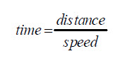
U.S. customary units example: If you’re 140 miles away from your destination, and you’re traveling 70 miles per hour, it’s going to take 2 hours to get there.
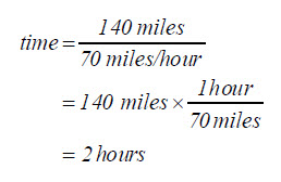
Metric units example: If you’re 200 kilometers away from your destination, and you’re traveling 100 kilometers per hour, it’s going to take 2 hours to get there.
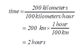
You can do the same exercise with the BOE Shield-Bot, except you have control over how far away the destination is. Here’s the equation you will use:
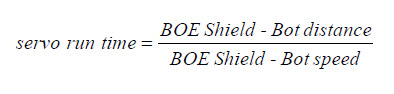
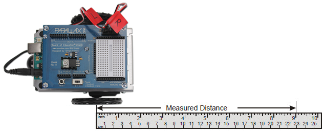
// Robotics with the BOE Shield - ForwardOneSecond
// Make the BOE Shield-Bot roll forward for one seconds, then stop.

#include <Servo.h>                           // Include servo library

Servo servoLeft;                             // Declare left and right servos
Servo servoRight;

void setup()                                 // Built-in initialization block
{
  tone(4, 3000, 1000);                       // Play tone for 1 second
  delay(1000);                               // Delay to finish tone

  servoLeft.attach(13);                      // Attach left signal to pin 13
  servoRight.attach(12);                     // Attach right signal to pin 12
                                             // Full speed forward
  servoLeft.writeMicroseconds(1700);         // Left wheel counterclockwise
  servoRight.writeMicroseconds(1300);        // Right wheel clockwise
  delay(1000);                               // ...for 1 second

  servoLeft.detach();                        // Stop sending servo signals
  servoRight.detach();
}

void loop()                                  // Main loop auto-repeats
{                                            // Empty, nothing needs repeating
}
The distance you just recorded is your BOE Shield-Bot’s speed, in units per second. Now, you can figure out how many seconds your BOE Shield-Bot has to travel to go a particular distance.
Inches and centimeters per second
The abbreviation for inches is in, and the abbreviation for centimeters is cm. Likewise, inches per second is abbreviated in/s, and centimeters per second is abbreviated cm/s. Both are convenient speed measurements for the BOE Shield-Bot. There are 2.54 cm in 1 in. You can convert inches to centimeters by multiplying the number of inches by 2.54. You can convert centimeters to inches by dividing the number of centimeters by 2.54
Keep in mind that your calculations will be in terms of seconds, but the delay function will need a parameter that’s in terms of milliseconds. So, take your result, which is in terms of seconds, and multiply it by 1000. Then, use that value in your delay function call. For example, to make your BOE Shield-Bot run for 2.22 seconds, you’d use delay(2220) after your writeMicroseconds calls.
U.S. customary units example: At 9 in/s, your BOE Shield-Bot has to travel for 2.22 s to travel 20 in.
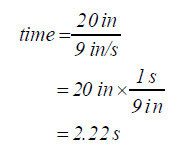
Metric units example: At 23 cm/s, your BOE Shield-Bot has to travel for 2.22 s to travel 51 cm.
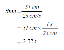
Both examples above resolve to the same answer:
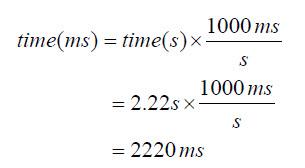
So, use delay(2220) after your writeMicroseconds calls:
  servoLeft.writeMicroseconds(1700);
  servoRight.writeMicroseconds(1300);
  delay(2220);
Now it’s time to try this out with distances that you choose.
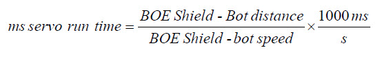
Increase the accuracy of your BOE Shield-Bot distances with devices called encoders which count the holes in the BOE Shield-Bot’s wheels as they pass.
Ramping is a way to gradually increase or decrease the speed of the servos instead of abruptly starting or stopping. This technique can increase the life expectancy of both your BOE Shield-Bot’s batteries and your servos.
The diagram below shows an example of how to ramp up to full speed. The for loop declares an int variable named speed, and uses it to repeat the loop 100 times. With each repetition of the loop, the value of speed increases by 2 because of the speed+=2 expression in the for loop’s increment parameter. Since the speed variable is in each writeMicroseconds call’s us parameter, it affects the value each time the for loop repeats. With the 20 ms delay between each repetition, the loop repeats at about 50 times per second. That means it takes speed 1 second to get to 100 in steps of 2, and at that point, both servos will be going about full speed.
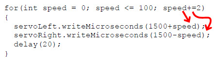
Let’s take a closer look at the trips through the for loop from this diagram:
// Robotics with the BOE Shield - StartAndStopWithRamping
// Ramp up, go forward, ramp down.

#include <Servo.h>                           // Include servo library

Servo servoLeft;                             // Declare left and right servos
Servo servoRight;

void setup()                                 // Built-in initialization block
{
  tone(4, 3000, 1000);                       // Play tone for 1 second
  delay(1000);                               // Delay to finish tone

  servoLeft.attach(13);                      // Attach left signal to pin 13
  servoRight.attach(12);                     // Attach right signal to pin 12

  for(int speed = 0; speed <= 100; speed += 2) // Ramp up to full speed.
  {
    servoLeft.writeMicroseconds(1500+speed);   // us = 1500,1502,...1598,1600
    servoRight.writeMicroseconds(1500-speed);  // us = 1500,1498,...1402,1400
    delay(20);                                 // 20 ms at each speed
  }

  delay(1500);                                 // Full speed for 1.5 seconds

  for(int speed = 100; speed >= 0; speed -= 2) // Ramp from full speed to stop
  {
    servoLeft.writeMicroseconds(1500+speed);   // us = 1600,1598,...1502,1500
    servoRight.writeMicroseconds(1500-speed);  // us = 1400,1402,...1498,1500
    delay(20);                                 // 20 ms at each speed
  }

  servoLeft.detach();                          // Stop sending servo signals
  servoRight.detach();
}

void loop()                                    // Main loop auto-repeats
{                                              // Empty, nothing to repeat
}
You can also create routines to combine ramping with other maneuvers. Here’s an example of how to ramp up to full speed going backward instead of forward. The only difference between this routine and the forward ramping routine is that the value of speed starts at zero and counts to –100.
  for(int speed = 0; speed >= -100; speed -= 2)// Ramp stop to full reverse
  {
    servoLeft.writeMicroseconds(1500+speed);   // us = 1500,1498, 1496...1400
    servoRight.writeMicroseconds(1500-speed);  // us = 1500,1502, 1508...1600
    delay(20);                                 // 20 ms at each speed
  }
You can also make a routine for ramping into and out of a turn. Here is a right-turn ramping example. Notice that instead of 1500+speed for one wheel and 1500–speed for the other, now they are both 1500+speed. For left-turn ramping, they would both be 1500–speed.
  for(int speed = 0; speed <= 100; speed += 2) // Ramp stop to right turn
  {
    servoLeft.writeMicroseconds(1500+speed);   // us = 1500,1502, 1508...1600
    servoRight.writeMicroseconds(1500+speed);  // us = 1500,1502, 1508...1600
    delay(20);                                 // 20 ms at each speed
  }

  for(int speed = 100; speed >= 0; speed -= 2)// right turn to stop
  {
    servoLeft.writeMicroseconds(1500+speed);   // us = 1600,1598, 1597...1500
    servoRight.writeMicroseconds(1500+speed);  // us = 1600,1598, 1597...1500
    delay(20);                                 // 20 ms at each speed
  }
One convenient way to execute pre-programmed maneuvers is with functions. In the next chapter, your BOE Shield-Bot will have to perform maneuvers to avoid obstacles, and a key ingredient for avoiding obstacles is executing pre-programmed maneuvers.
The setup and loop functions are built into the Arduino language, but you can add more functions that do specific tasks for your sketch. This activity introduces how to add more functions to your sketch as well as a few different approaches to creating reusable maneuvers with those functions.
The diagram below shows part of a sketch that contains a function named example added at the end, below the loop function. It begins and gets named with the function definition void example(). The empty parentheses means that it doesn’t need any parameters to do its job, and void indicates that it does not return a value (we’ll look at functions that return values in a later chapter). The curly braces {} that follow this definition contain the example function’s block of code.

There is a function call to example in the setup function, labeled in the diagram above. That example() line tells the sketch to go find the function with that name, execute its code, and come back when done. So, the sketch jumps down to void example() and executes the two commands in its curly braces. Then, it returns to the function call and continues from there. Here is the order of events you will see when you run the sketch:
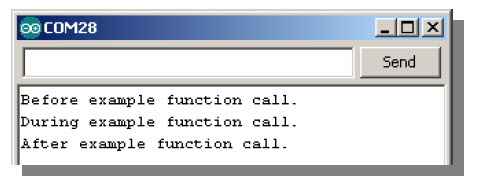
// Robotics with the BOE Shield – SimpleFunctionCall
// This sketch demonstrates a simple function call.

void setup() {
  Serial.begin(9600);

  Serial.println("Before example function call.");
  delay(1000);

  example();                              // This is the function call

  Serial.println("After example function call.");
  delay(1000);
}

void loop() {
}

void example()                            // This is the function
{
  Serial.println("During example function call.");
  delay(1000);
}
Remember that a function can have one or more parameters—data that the function receives and uses when it is called. The diagram below shows the pitch function from the next sketch. It is declared with void pitch(int Hz). Recall from Chapter 1, Activity #3 that the Arduino stores variable values in different data types, with int specifying an integer value in the range of -32,768 to 32,767. Here, the term int Hz in the parentheses defines a parameter for the pitch function; in this case, it declares a local variable Hz of data type int.
Local variables, remember, are declared within a function, and can only be seen and used inside that function. If a local variable is created as a parameter in the function declaration, as void pitch(int Hz) is here, initialize it by passing a value to it each time the function is called. For example, the call pitch(3500) passes the integer value 3500 to the pitch function’s int Hz parameter.
So, when the first function call to pitch is made with pitch(3500), the integer value 3500 gets passed to Hz. This initializes Hz to the value 3500, to be used during this trip through the pitch function’s code block. The second call, pitch(2000), initializes Hz to 2000 during the sketch’s second trip through the pitch function’s code block.
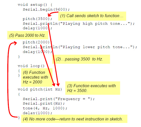
// Robotics with the BOE Shield – FunctionCallWithParameter
// This program demonstrates a function call with a parameter.

void setup() {
  Serial.begin(9600);

  Serial.println("Playing higher pitch tone...");

  pitch(3500);         // pitch function call passes 3500 to Hz parameter

  delay(1000);

  Serial.println("Playing lower pitch tone...");

  pitch(2000);         // pitch function call passes 2000 to Hz parameter

  delay(1000);
}

void loop()
{
}

void pitch(int Hz)     // pitch function with Hz declared as a parameter
{
  Serial.print("Frequency = ");
  Serial.println(Hz);
  tone(4, Hz, 1000);
  delay(1000);
}
Here is a modified pitch function that accepts two parameters: Hz and ms. This new pitch function controls how long the tone lasts.
void pitch(int Hz, int ms)
{
  Serial.print("Frequency = ");
  Serial.println(Hz);
  tone(4, Hz, ms);
  delay(ms);
}
Here are two calls to the modified pitch function, one for a 0.5 second 3500 Hz tone, and the other for a 1.5 second 2000 Hz tone:
pitch(3500, 500);
pitch(2000, 1500);
Notice that each of these calls to pitch includes two values, one to pass to the Hz parameter, and one to pass to the ms parameter. The number of values in a function call must match the number of parameters in that function’s definition, or the sketch won’t compile.
Let’s try putting the forward, turnLeft, turnRight, and backward navigation routines inside functions. Here’s an example:
// Robotics with the BOE Shield - MovementsWithSimpleFunctions
// Move forward, left, right, then backward for testing and tuning.

#include <Servo.h>                           // Include servo library

Servo servoLeft;                             // Declare left and right servos
Servo servoRight;

void setup()                                 // Built-in initialization block
{
  tone(4, 3000, 1000);                       // Play tone for 1 second
  delay(1000);                               // Delay to finish tone

  servoLeft.attach(13);                      // Attach left signal to pin 13
  servoRight.attach(12);                     // Attach right signal to pin 12

  forward(2000);                             // Go forward for 2 seconds
  turnLeft(600);                             // Turn left for 0.6 seconds
  turnRight(600);                            // Turn right for 0.6 seconds
  backward(2000);                            // go backward for 2 seconds

  disableServos();                           // Stay still indefinitely
}

void loop()                                  // Main loop auto-repeats
{                                            // Empty, nothing needs repeating
}

void forward(int time)                       // Forward function
{
  servoLeft.writeMicroseconds(1700);         // Left wheel counterclockwise
  servoRight.writeMicroseconds(1300);        // Right wheel clockwise
  delay(time);                               // Maneuver for time ms
}

void turnLeft(int time)                      // Left turn function
{
  servoLeft.writeMicroseconds(1300);         // Left wheel clockwise
  servoRight.writeMicroseconds(1300);        // Right wheel clockwise
  delay(time);                               // Maneuver for time ms
}

void turnRight(int time)                     // Right turn function
{
  servoLeft.writeMicroseconds(1700);         // Left wheel counterclockwise
  servoRight.writeMicroseconds(1700);        // Right wheel counterclockwise
  delay(time);                               // Maneuver for time ms
}

void backward(int time)                      // Backward function
{
  servoLeft.writeMicroseconds(1300);         // Left wheel clockwise
  servoRight.writeMicroseconds(1700);        // Right wheel counterclockwise
  delay(time);                               // Maneuver for time ms
}

void disableServos()                         // Halt servo signals
{
  servoLeft.detach();                        // Stop sending servo signals
  servoRight.detach();
}
You should recognize the pattern of movement your BOE Shield-Bot makes; it is the same one made by the ForwardLeftRightBackward sketch. This is a second example of the many different ways to structure a sketch that will result in the same movements. There will be a few more examples before the end of the chapter.
Want to keep performing that set of four maneuvers over and over again? Just move those four maneuvering function calls from the setup function into the loop function. Try this:
Cut the function calls to forward(2000), turnLeft(600), turnRight(600), and backward(2000) out of the setup function and paste them into the loop function. It should look like this when you’re done:
void setup()                    // Built-in initialization block
{
  tone(4, 3000, 1000);          // Play tone for 1 second
  delay(1000);                  // Delay to finish tone

  servoLeft.attach(13);         // Attach left signal to pin 13
  servoRight.attach(12);        // Attach right signal to pin 12

  // disableServos();             // Stay still indefinitely
}

void loop()                     // Main loop auto-repeats
{
  forward(2000);                // Go forward for 2 seconds
  turnLeft(600);                // Turn left for 0.6 seconds
  turnRight(600);               // Turn right for 0.6 seconds
  backward(2000);               // go backward for 2 seconds
The last sketch, MovementsWithSimpleFunctions, was kind of long and clunky. And, the four functions it uses to drive the robot are almost the same. The TestManeuverFunction sketch takes advantage of those function’s similarities and streamlines the code.
TestManeuverFunction has a single function for motion named maneuver that accepts three parameters: speedLeft, speedRight, and msTime:
void maneuver(int speedLeft, int speedRight, int msTime)
The rules for speedLeft and speedRight, listed below, are easy to remember. Best of all, with this maneuver function you don’t have to think about clockwise and counterclockwise rotation anymore.
The rules for msTime are:
Here is what calls to this function will look like for the familiar forward-backward-left-right-stop sequence:
maneuver(200, 200, 2000);           // Forward 2 seconds
maneuver(-200, 200, 600);           // Left 0.6 seconds
maneuver(200, -200, 600);           // Right 0.6 seconds
maneuver(-200, -200, 2000);         // Backward 2 seconds
maneuver(0, 0, -1);                 // Disable servos
// Robotics with the BOE Shield - TestManeuverFunction
// Move forward, left, right, then backward with maneuver function.

#include <Servo.h>                           // Include servo library

Servo servoLeft;                             // Declare left and right servos
Servo servoRight;

void setup()                                 // Built-in initialization block
{
  tone(4, 3000, 1000);                       // Play tone for 1 second
  delay(1000);                               // Delay to finish tone

  servoLeft.attach(13);                      // Attach left signal to pin 13
  servoRight.attach(12);                     // Attach right signal to pin 12

  maneuver(200, 200, 2000);                  // Forward 2 seconds
  maneuver(-200, 200, 600);                  // Left 0.6 seconds
  maneuver(200, -200, 600);                  // Right 0.6 seconds
  maneuver(-200, -200, 2000);                // Backward 2 seconds
  maneuver(0, 0, -1);                        // Disable servos
}

void loop()                                  // Main loop auto-repeats
{                                            // Empty, nothing needs repeating
}

void maneuver(int speedLeft, int speedRight, int msTime)
{
  // speedLeft, speedRight ranges: Backward  Linear  Stop  Linear   Forward
  //                               -200      -100......0......100       200
  servoLeft.writeMicroseconds(1500 + speedLeft);   // Set Left servo speed
  servoRight.writeMicroseconds(1500 - speedRight); // Set right servo speed
  if(msTime==-1)                                   // if msTime = -1
  {
    servoLeft.detach();                            // Stop servo signals
    servoRight.detach();
  }
  delay(msTime);                                   // Delay for msTime
}
With the maneuver function, 0 is stop, 100 to –100 is the speed control range, and 200 and –200 are overkill to keep the servos running as fast as they possibly can.
The TestManeuverFunction sketch makes it easy to define custom maneuvers quickly. Just pass new parameters for each wheel rotation and maneuver duration to each call of the maneuver function. For example, let’s make the left wheel move at half speed while the right wheel moves at full speed to draw an arc for 3 seconds. Here is what that function call would look like:
maneuver(50, 100, 3000);
Here is another example that keeps the left wheel still and moves the right wheel forward for a left pivot turn:
maneuver(0, 200, 1200);
Some robotics applications require sequences of maneuvers. You’ll actually see some simple sequence examples in the next chapter when the BOE Shield-Bot detects that it has bumped into an obstacle. At that point, it has to back up, and then turn before trying to go forward again. That is a simple sequence with two maneuvers.
Another example is corridor navigation. The BOE Shield-Bot might have to find a corridor and then go through a sequence of maneuvers to enter it, before searching for the corridor’s walls.
Other sequences can be more elaborate. One example of a long and complex maneuver would be for a robotic dance contest. (Robot dance contests have been gaining popularity in recent years.) For dancing to an entire song, the robot might need a pretty long list of maneuvers and maneuver times. If your sketch needs to store lists of maneuvers, the variable array is the best tool for storing these lists.
This activity introduces arrays with some simple musical applications using the piezospeaker. Then, it examines two different approaches for using arrays to store sequences of maneuvers for playback while the sketch is running.
An array is a collection of variables with a common name. Each variable in the array is referred to as an element. Here is an array declaration with eight elements:
int note[] = {1047, 1174, 1319, 1397, 1568, 1760, 1976, 2093};
The array’s name is note, and each element in the array can be accessed by its index number. Arrays are zero indexed, so the elements are numbered 0 to 7. The diagram below shows how note[0] stores 1047, note[1] stores 1174, note[2] stores 1319, and so on, up through note[7], which stores 2093.
Let’s say your code needs to copy note[3], which stores the value 1397, to a variable named myVar. Your code could do it like this:
myVar = note[3];
Your sketch can change array element values too. For example, you could change the value 1976 to 1975 with an expression like this:
note[3] = 1975;
An array does not have to be pre-initialized with values like it is in the diagram above. For example, you could just declare an array with 8 elements like this:
int myArray[8];
Then, your sketch could fill in the values of each element later, perhaps with sensor measurements, values entered from the Serial Monitor, or whatever numbers you need to store.
The diagram below shows the musical notes on the right side of a piano keyboard. Each key press on a piano key makes a string (or a speaker if it’s electric) vibrate at a certain frequency.
Next, let’s use the array to make your BOE Shield-Bot play some musical notes…
An array element doesn’t necessarily need to be copied to another variable to use its value. For example, your sketch could just print the value in note[3] to the Serial Monitor like this:
Serial.print(note[3]);
Since the values in the array are musical notes, we might as well play this note on the BOE Shield-Bot’s piezospeaker! Here’s how:
tone(4, note[3], 500);
Here is an example that displays an individual array element’s value in the Serial Monitor, and also uses that value to make the BOE Shield-Bot’s piezospeaker play a musical note.
// Robotics with the BOE Shield – PlayOneNote
// Displays and plays one element from note array.

int note[] = {1047, 1147, 1319, 1397, 1568, 1760, 1976, 2093};

void setup()
{
  Serial.begin(9600);

  Serial.print("note = ");
  Serial.println(note[3]);

  tone(4, note[3], 500);
  delay(750);
}

void loop()
{
}
Many applications use variables to access elements in an array. The next sketch PlayAnotherNote declares a variable named index and uses it to select an array element by its index number.
The familiar for loop can automatically increment the value of index. The code to play and display notes is inside the for loop, and index is used to select the array element. For the first trip through the loop, index will be 0, so the value stored in note[0] will be used wherever note[index] appears in a print or tone function. With each trip through the loop, index will increment until the sketch has displayed and played all the notes in the array.
// Robotics with the BOE Shield – PlayNotesWithLoop
// Displays and plays another element from note array.

int note[] = {1047, 1147, 1319, 1397, 1568, 1760, 1976, 2093};

void setup()
{

  Serial.begin(9600);

  for(int index = 0; index < 8; index++)
  {
    Serial.print("index = ");
    Serial.println(index);

    Serial.print("note[index] = ");
    Serial.println(note[index]);

    tone(4, note[index], 500);
    delay(750);
  }
}

void loop()
{
}
for(int index = 7; index >= 0; index--);
Let’s say you want to compose a musical melody that has more, or fewer, notes. It’s easy to forget to update the for loop to play the correct number of notes. The Arduino library has a sizeof function that can help with this. It can tell you both the size of the array in bytes, and the size of the array’s variable type (like int). Your code can then divide the number of bytes for the variable type into the number of bytes in the array. The result is the number of elements in the array.
Here is an example of using this technique. It loads a variable named elementCount with the number of elements in the note array:
int note[] = {1047, 1147, 1319, 1397, 1568, 1760, 1976, 2093};
int elementCount = sizeof(note) / sizeof(int);
Later, your for loop can use the elementCount variable to play all the notes in the array, even if you add or delete elements:
for(int index = 0; index < elementCount; index++)
// Robotics with the BOE Shield – PlayAllNotesInArray
// Uses sizeof to determine number of elements int he array
// and then displays and prints each note value in the sequence.

int note[] = {1047, 1147, 1319, 1397, 1568, 1760, 1976, 2093};

void setup()
{
  Serial.begin(9600);

  int elementCount = sizeof(note) / sizeof(int);

  Serial.print("Number of elements in array = ");
  Serial.println(elementCount);

  for(int index = 0; index < elementCount; index++)
  {
    Serial.print("index = ");
    Serial.println(index);

    Serial.print("note[index] = ");
    Serial.println(note[index]);

    tone(4, note[index], 500);
    delay(750);
  }
}

void loop()
{
}
  int note[] = {1047, 1147, 1319, 1397, 1568, 1760,
                1976, 2093, 2349, 2637};
Remember the maneuver function from the last activity? Here are three arrays of values, one for each parameter in the maneuver function. Together, they make up the same forward-left-right-backward-stop sequence we’ve been doing through the chapter.
  //                Forward    left   right   backward    stop
  //         index        0       1       2          3       4
  int speedsLeft[]  = {200,    -200,    200,      -200,      0};
  int speedsRight[] = {200,     200,   -200,      -200,      0};
  int times[]       = {2000,    600,    600,      2000,     -1};
A sketch can then use this code in one of its functions to execute all the maneuvers:
  // Determine number of elements in sequence list.
  int elementCount = sizeof(times) / sizeof(int);

  // Fetch successive elements from each sequence list and feed them
  // to maneuver function.
  for(int index = 0; index < elementCount; index++)
  {
    maneuver(speedsLeft[index], speedsRight[index], times[index]);
  }
Each time through the loop, index increases by 1. So, with each maneuver call, the next element in each array gets passed as a parameter to the maneuver function. The first time through the loop, index is 0, so the maneuver call’s parameters become the zeroth element from each array, like this: maneuver(speedsLeft[0], speedsRight[0], times[0]). The actual values that get passed to the maneuver function look like this: maneuver(200, 200, 2000). The second time through the loop, index is 1, so the function looks like this: maneuver(speedsLeft[1], speedsRight[1], times[1]), which becomes maneuver(–200, 200, 2000).
// Robotics with the BOE Shield - ManeuverSequence
// Move forward, left, right, then backward with an array and the
// maneuver function.

#include <Servo.h>                           // Include servo library

//                Forward    left   right   backward    stop
//         index        0       1       2          3       4
int speedsLeft[]  = {200,    -200,    200,      -200,      0};
int speedsRight[] = {200,     200,   -200,      -200,      0};
int times[]       = {2000,    600,    600,      2000,     -1};

Servo servoLeft;                             // Declare left and right servos
Servo servoRight;

void setup()                                 // Built-in initialization block
{
  tone(4, 3000, 1000);                       // Play tone for 1 second
  delay(1000);                               // Delay to finish tone

  servoLeft.attach(13);                      // Attach left signal to pin 13
  servoRight.attach(12);                     // Attach right signal to pin 12

  // Determine number of elements in sequence list.
  int elementCount = sizeof(times) / sizeof(int);

  // Fetch successive elements from each sequence list and feed them
  // to maneuver function.
  for(int index = 0; index < elementCount; index++)
  {
    maneuver(speedsLeft[index], speedsRight[index], times[index]);
  }
}

void loop()                                  // Main loop auto-repeats
{                                            // Empty, nothing needs repeating
}

void maneuver(int speedLeft, int speedRight, int msTime)
{
  // speedLeft, speedRight ranges: Backward  Linear  Stop  Linear   Forward
  //                               -200      -100......0......100       200
  servoLeft.writeMicroseconds(1500 + speedLeft);   // Set Left servo speed
  servoRight.writeMicroseconds(1500 - speedRight); // Set right servo speed
  if(msTime==-1)                                   // if msTime = -1
  {
    servoLeft.detach();                            // Stop servo signals
    servoRight.detach();
  }
  delay(msTime);                                   // Delay for msTime
}
Did your BOE Shield-Bot perform the familiar forward-left-right-backward-stop sequence of movements? Are you thoroughly bored with it by now? Do you want to see your BOE Shield-Bot do something else, or to choreograph your own routine?
Here’s an example of a longer list you can try. It does the four pivots after the forward-left-right-backward sequence. In this example, when index is 4, it’ll use the first number of the second line of each array. When index is 5, it’ll use the second number on the second line of each array, and so on. Notice that each list of comma-separated array elements is contained within braces { }, and it doesn’t matter whether that list is all on one line or spanning multiple lines.
int speedsLeft[]  = {200,    -200,    200,      -200,
                       0,     200,   -200,        0,       0};
int speedsRight[] = {200,     200,   -200,      -200,
                     200,       0,      0,      -200,      0};
int times[]       = {2000,    600,    600,      2000,
                     1000,   1000,   1000,      1000,     -1};
The last example in this activity a sketch for performing maneuvers using a list of characters in an array. Each character represents a certain maneuver, with a 200 ms run time. Since the run time is fixed, it’s not as flexible as the last approach, but it sure makes it simple to build a quick sequence of maneuvers.
f = forward b = backward l = left r = right s = stop
Character arrays use do not use lists of comma-separated elements. Instead, they use a continuous string of characters. Here is an example of the same-old forward-left-right-backward-stop sequence in a character array:
char maneuvers[] = "fffffffffflllrrrbbbbbbbbbbs";
The character array string has 10 f characters. Since each character represents 200 ms of run time, that takes the BOE Shield-Bot forward for 2 seconds. Next, three l characters make 600 ms of left turn. Three r characters make a right turn, followed by ten b characters to go backward, and then an s character for stop completes the sequence.
// Robotics with the BOE Shield – ControlWithCharacters
// Move forward, left, right, then backward for testing and tuning.

#include <Servo.h>                           // Include servo library

char maneuvers[] = "fffffffffflllrrrbbbbbbbbbbs";

Servo servoLeft;                             // Declare left and right servos
Servo servoRight;

void setup()                                 // Built-in initialization block
{
  tone(4, 3000, 1000);                       // Play tone for 1 second
  delay(1000);                               // Delay to finish tone

  servoLeft.attach(13);                      // Attach left signal to P13
  servoRight.attach(12);                     // Attach right signal to P12

  // Parse maneuvers and feed each successive character to the go function.
  int index = 0;
  do
  {
    go(maneuvers[index]);
  } while(maneuvers[index++] != 's');}

void loop()                                  // Main loop auto-repeats
{                                            // Empty, nothing needs repeating
}

void go(char c)                              // go function
{
  switch(c)                                  // Switch to code based on c
  {
    case 'f':                                // c contains 'f'
      servoLeft.writeMicroseconds(1700);     // Full speed forward
      servoRight.writeMicroseconds(1300);
      break;
    case 'b':                                // c contains 'b'
      servoLeft.writeMicroseconds(1300);     // Full speed backward
      servoRight.writeMicroseconds(1700);
      break;
    case 'l':                                // c contains 'l'
      servoLeft.writeMicroseconds(1300);     // Rotate left in place
      servoRight.writeMicroseconds(1300);
      break;
    case 'r':                                // c contains 'r'
      servoLeft.writeMicroseconds(1700);     // Rotate right in place
      servoRight.writeMicroseconds(1700);
      break;
    case 's':                                // c contains 's'
      servoLeft.writeMicroseconds(1500);     // Stop
      servoRight.writeMicroseconds(1500);
      break;
  }
  delay(200);                                 // Execute for 0.2 seconds
}
char maneuvers[] = "fffffffffflllrrrrrrlllbbbbbbbbbbs";
After the char maneuvers array and the usual initialization, these lines fetch the characters from the array and pass them to the go function (explained later).
  int index = 0;
  do
  {
    go(maneuvers[index]);
  } while(maneuvers[index++] != 's');
First, index is declared and initialized to zero, to be used in a do-while loop. Similar to a regular while loop, do-while repeatedly executes commands inside its code block while a condition is true, but the while part comes after its block so the block always executes at least once. Each time through the loop, go(maneuvers[index]) passes the character at maneuvers[index] to the go function. The ++ in index++ adds one to the index variable for the next time through the loop—recall that this is the post increment operator. This continues while(maneuvers[index] != ‘s’) which means “while the value fetched from the maneuvers array is not equal to ‘s’ .”
Now, let’s look at the go function. It receives each character passed to its c parameter, and evaluates it on a case-by-case basis using a switch/case statement. For each of the five letters in the maneuvers character array, there is a corresponding case statement in the switch(c) block that will be executed if that character is received by go.
If the go function call passes the f character to the c parameter, the code in case f is executed—the familiar full-speed-forward. If it passes b, the full-speed backward code gets executed. The break in each case exits the switch block and the sketch moves on to the next command, which is delay(200). So, each call to go results in a 200 ms maneuver. Without that break at the end of each case, the sketch would continue through to the code for the next case, resulting in un-requested maneuvers.
void go(char c)                              // go function
{
  switch(c)                                  // Switch to based on c
  {
    case 'f':                                // c contains 'f'
      servoLeft.writeMicroseconds(1700);     // Full speed forward
      servoRight.writeMicroseconds(1300);
      break;
    case 'b':                                // c contains 'b'
      servoLeft.writeMicroseconds(1300);     // Full speed backward
      servoRight.writeMicroseconds(1700);
      break;
    case 'l':                                // c contains 'l'
      servoLeft.writeMicroseconds(1300);     // Rotate left in place
      servoRight.writeMicroseconds(1300);
      break;
    case 'r':                                // c contains 'r'
      servoLeft.writeMicroseconds(1700);     // Rotate right in place
      servoRight.writeMicroseconds(1700);
      break;
    case 's':                                // c contains 's'
      servoLeft.writeMicroseconds(1500);     // Stop
      servoRight.writeMicroseconds(1500);
      break;
  }
  delay(200);                                 // Execute for 0.2 s
case 'h':                                // c contains 'h'
  servoLeft.writeMicroseconds(1550);     // Half speed forward
  servoRight.writeMicroseconds(1450);
  break;
This chapter was all about robot navigation, experimenting with many different programming approaches and employing some robotics and engineering skills:
Programming
Robotics Skills
Engineering Skills
servoLeft.writeMicroseconds(1500);
servoRight.writeMicroseconds(1300);
BOE Shield-Bot speed = 11 in/s
BOE Shield-Bot distance = 36 in/s
time = (BOE Shield-Bot distance / BOE Shield-Bot speed) * (1000 ms / s)
= (36 / 11 ) * (1000)
= 3.727272…s * 1000 ms/s
≈ 3727 ms
servoLeft.writeMicroseconds(1300);
servoRight.writeMicroseconds(1700);
delay(2500);
// 30/180 = 1/6, so use 1200/6 = 200
servoLeft.writeMicroseconds(1700);
servoRight.writeMicroseconds(1700);
delay(200);

// alternate approach
servoLeft.writeMicroseconds(1700);
servoRight.writeMicroseconds(1700);
delay(1200 * 30 / 180);

// 45/180 = 1/4, so use 1200/4 = 300
servoLeft.writeMicroseconds(1700);
servoRight.writeMicroseconds(1700);
delay(300);

// 60/180 = 1/3, so use 1200/3 = 400
servoLeft.writeMicroseconds(1700);
servoRight.writeMicroseconds(1700);
delay(400);
// forward 1 second
servoLeft.writeMicroseconds(1700);
servoRight.writeMicroseconds(1700);
delay(1000);

// ramp into pivot
for(int speed = 0; speed <= 100; speed+=2)
{
  servoLeft.writeMicroseconds(1500);
  servoRight.writeMicroseconds(1500+speed);
  delay(20);
};

// ramp out of pivot
for(int speed = 100; speed >= 0; speed-=2)
{
  servoLeft.writeMicroseconds(1500);
  servoRight.writeMicroseconds(1500+speed);
  delay(20);
}

// forward again
servoLeft.writeMicroseconds(1700);
servoRight.writeMicroseconds(1700);
delay(1000);

For the triangle, First calculate the required travel time in ms for a 1 meter or 1 yard straight line, as in Question 4, and fine-tune for your BOE Shield-Bot and particular surface. The BOE Shield-Bot must travel 1 meter/yard forward, and then make a 120° turn, repeated three times for the three sides of the triangle. You may have to adjust the delay call in the Turn Left 120° routine to get a precise 120° turn.
Circle sketch:
// Robotics with the BOE Shield - Chapter 4, project 2 - Circle
// BOE Shield-Bot navigates a circle of  1 yard diameter.

#include <Servo.h>                    // Include servo library

Servo servoLeft;                      // Declare left and right servos
Servo servoRight;

void setup()                          // Built-in initialization block
{
  tone(4, 3000, 1000);                // Play tone for 1 second
  delay(1000);                        // Delay to finish tone

  servoLeft.attach(13);               // Attach left signal to pin 13
  servoRight.attach(12);              // Attach right signal to pin 12

  // Arc to the right
  servoLeft.writeMicroseconds(1600);  // Left wheel counterclockwise
  servoRight.writeMicroseconds(1438); // Right wheel clockwise slower
  delay(25500);                       // ...for 25.5 seconds

  servoLeft.detach();                 // Stop sending servo signals
  servoRight.detach();
}

void loop()                          // Main loop auto-repeats
{                                    // Nothing needs repeating
}
Triangle sketch:
// Robotics with the BOE Shield - Chapter 4, project 2 - Triangle
// BOE Shield-Bot navigates a triangle with 1 yard sides and 120
// degree angles.  Go straight 1 yard, turn 120 degrees, repeat 3 times

#include <Servo.h>                    // Include servo library

Servo servoLeft;                      // Declare left and right servos
Servo servoRight;

void setup()                          // Built-in initialization block
{
  tone(4, 3000, 1000);                // Play tone for 1 second
  delay(1000);                        // Delay to finish tone

  servoLeft.attach(13);               // Attach left signal to pin 13
  servoRight.attach(12);              // Attach right signal to pin 12

  for(int index = 1; index <= 3; index++)
  {
    // Full speed forward
    servoLeft.writeMicroseconds(1700);  // Left wheel counterclockwise
    servoRight.writeMicroseconds(1300); // Right wheel clockwise slower
    delay(5500);                        // ...for 5.5 seconds

    // Turn left 120 degrees
    servoLeft.writeMicroseconds(1300);  // Left wheel counterclockwise
    servoRight.writeMicroseconds(1300); // Right wheel clockwise slower
    delay(700);
  }
  servoLeft.detach();                   // Stop sending servo signals
  servoRight.detach();
}

void loop()                             // Main loop auto-repeats
{                                       // Nothing needs repeating
}
Tactile switches are also called bumper switches or touch switches, and they have many uses in robotics. A robot programmed to pick up an object and move it to another conveyer belt might rely on a tactile switch to detect the object. Automated factory lines might use tactile switches to count objects, and to align parts for a certain step in a manufacturing process. In each case, switches provide inputs that trigger some form of programmed output. The inputs are electronically monitored by the equipments processor, which takes different actions depending on if the switch is pressed or not pressed.
In this chapter, you will build tactile switches, called whiskers, onto your BOE Shield-Bot and test them. You will then program the BOE Shield-Bot to monitor the states of these switches, and to decide what to do when it encounters an obstacle. The end result will be autonomous navigation by touch.
Whisker switches give the BOE Shield-Bot the ability to sense its surroundings through touch as it roams around, much like a cat’s whiskers. The activities in this chapter use the whiskers by themselves, but they can also be combined with other sensors you will learn about in later chapters.
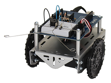
Remember subsystem testing? First, we’ll build the whiskers circuits and write code to check their input states before using them in navigation sketches.
(2) whisker wires
(2) 7/8″ pan head 4-40 Phillips screws
(2) ½″ round spacer
(2) nylon washers, size #4
(2) 3-pin m/m headers
(2) resistors, 220 Ω (red-red-brown)
(2) resistors, 10 kΩ (brown-black-orange)
(misc) jumper wires
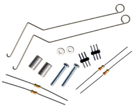
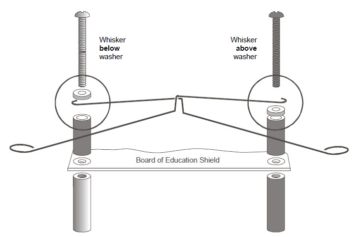
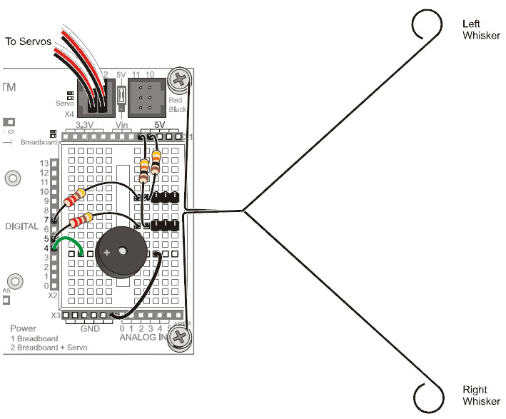
The whiskers are connected to ground (Vss) because the plated holes at the outer edge of the board are all connected to Vss. The metal standoffs and screws provide the electrical connection to each whisker.
Since each whisker is connected to digital I/O, the Arduino can be programmed to detect which voltage is applied to each circuit, 5 V or 0 V. First, set each pin to input mode with pinMode(pin, mode), and then detect the pin’s state, HIGH or LOW, with digitalRead(pin) function.
Take a look at the illustrations below. On the left, the circuit applies 5 V when the whisker is not pressed, so digitalRead(7) returns 1 (HIGH). On the right, the circuit applies 0 V when the whisker is pressed, so digitalRead(7) returns 0 (LOW).
Most importantly, your sketch can store the return values in variables, such as wLeft and wRight, and then use them to trigger actions or make decisions. The next example sketch will demonstrate how.
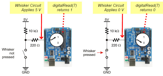
Switch Lingo: Each whisker is both the mechanical extension and the ground electrical connection of a normally open (off until pressed) momentary (on only while pressed) single-pole (one set of electrical contact points), single-throw (only one position conducts) switch.
The next sketch tests the whiskers to make sure they are functioning properly, by displaying the binary values returned by digitalRead(7) and digitalRead(5). This way, you can press each whisker against its 3-pin header on the breadboard, and see if the Arduino’s digital pin is sensing the electrical contact.
When neither whisker is pressed up against its 3-pin header, you can expect your Serial Monitor to display two columns of 1’s, one for each whisker. If you press just the right whisker, the right column should report 0, and the display should read 10. If you press just the left whisker, the left column should report 1 and the display should read 01. Of course, if you press both whiskers, it should display 00.
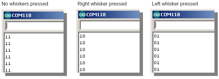
Active-low Output
The whisker circuits are wired for active-low output, which means that they each send a low signal when they are pressed (active) and a high signal when they are not pressed. Since digitalRead returns 0 for a low signal and 1 for a high signal, 0 is what tells your sketch that a whisker is pressed, and 1 tells it that a whisker is not pressed.
/*
 * Robotics with the BOE Shield - DisplayWhiskerStates
 * Display left and right whisker states in Serial Monitor.
 * 1 indicates no contact; 0 indicates contact.
 */

void setup()                                 // Built-in initialization block
{
  tone(4, 3000, 1000);                       // Play tone for 1 second
  delay(1000);                               // Delay to finish tone
  pinMode(7, INPUT);                         // Set right whisker pin to input
  pinMode(5, INPUT);                         // Set left whisker pin to input

  Serial.begin(9600);                        // Set data rate to 9600 bps
}

void loop()                                  // Main loop auto-repeats
{
  byte wLeft = digitalRead(5);               // Copy left result to wLeft
  byte wRight = digitalRead(7);              // Copy right result to wRight

  Serial.print(wLeft);                       // Display left whisker state
  Serial.println(wRight);                    // Display right whisker state

  delay(50);                                 // Pause for 50 ms
}
These steps are important!
Seriously, you’ve got to make sure your circuit and code pass these tests before continuing. The rest of the examples in this chapter rely on the whiskers working correctly. If you haven’t tested and corrected any errors, the rest of the examples won’t work right.
In the setup function, pinMode(7, INPUT) and pinMode(5, INPUT) set digital pins 7 and 5 to input so they can monitor the voltages applied by the whisker circuits.
  pinMode(7, INPUT);          // Set right whisker pin to input
  pinMode(5, INPUT);          // Set left whisker pin to input
In the loop function, each call to digitalRead returns a 0 if the whisker is pressed or 1 if it is not. Those values get copied to variables named wLeft and wRight, which are short for whisker-left and whisker-right.
  byte wLeft = digitalRead(5);     // Copy left result to wLeft
  byte wRight = digitalRead(7);    // Copy right result to wRight
Next, Serial.print displays the value of wLeft to the Serial Monitor, and Serial.println displays the value of wRight and a carriage return.
  Serial.print(wLeft);             // Display left whisker state
  Serial.println(wRight);          // Display right whisker state
Before the next repetition of the loop function, there’s a delay(50). This slows down the number of messages the Serial Monitor receives each second. Although it’s probably not needed, we leave it in to prevent possible computer buffer overruns (too much data to store) for older hardware and certain operating systems.
Your sketch doesn’t actually need to use variables to store the values from digitalRead. Instead, the (1 or 0) value that digitalRead returns can be used directly by nesting the function call inside Serial.print and sending its return value straight to the Serial Monitor. In that case, your loop function would look like this:
void loop()                        // Main loop auto-repeats
{
  Serial.print(digitalRead(5));    // Display wLeft
  Serial.println(digitalRead(7));  // Display wRight

  delay(50);                       // Pause for 50 ms
}
What if you have to test the whiskers at some later time away from a computer? In that case, the Serial Monitor won’t be available, so what can you do? One solution would be to use LED circuits to display the whisker states. All it takes is a simple sketch that turns an LED on when a whisker is pressed or off when it’s not pressed.
(2) resistors, 220 Ω (red-red-brown)
(2) LEDs, red
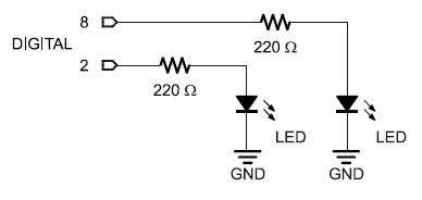
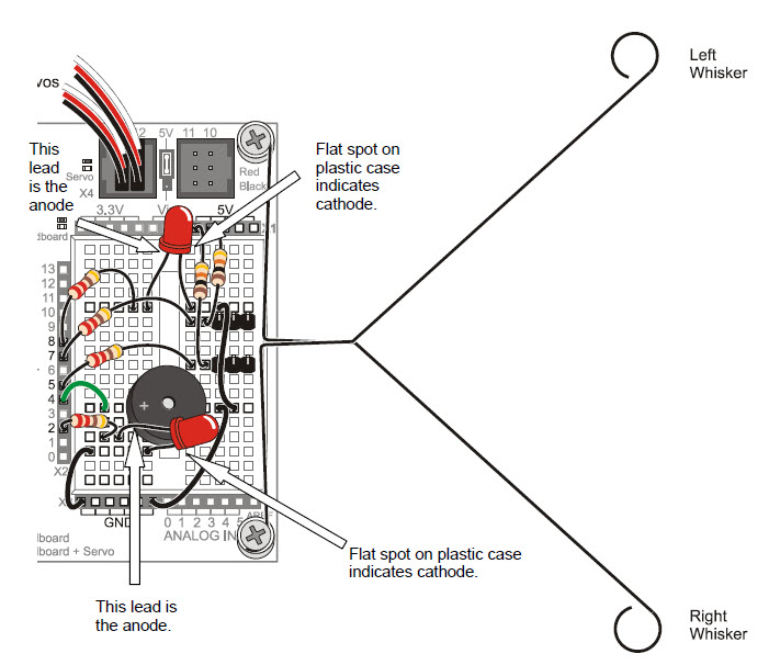
  pinMode(8, OUTPUT);         // Left LED indicator -> output
  pinMode(2, OUTPUT);         // Right LED indicator -> output
  if(wLeft == 0)              // If left whisker contact
  {
    digitalWrite(8, HIGH);    // Left LED on
  }
  else                        // If no left whisker contact
  {
    digitalWrite(8, LOW);     // Left LED off
  }

  if(wRight == 0)             // If right whisker contact
  {
    digitalWrite(2, HIGH);    // Right LED on
  }
  else                        // If no right whisker contact
  {
    digitalWrite(2, LOW);     // Right LED off
  }
Recall that if…else statements execute blocks of code based on conditions. Here, if wLeft stores a zero, it executes the digitalWrite(8, HIGH) call. If wLeft instead stores a 1, it executes the digitalWrite(8, LOW) call. The result? The left LED turns on when the left whisker is pressed or off when it’s not pressed. The second if…else statement does the same job with wRight and the right LED circuit.
/*
 * Robotics with the BOE Shield - TestWhiskersWithLeds
 * Display left and right whisker states in Serial Monitor.
 * 1 indicates no contact; 0 indicates contact.
 * Display whisker states with LEDs.  LED on indicates contact;
 * off indicates none.
 */

void setup()                                 // Built-in initialization block
{
  pinMode(7, INPUT);                         // Set right whisker pin to input
  pinMode(5, INPUT);                         // Set left whisker pin to input
  pinMode(8, OUTPUT);                        // Left LED indicator -> output
  pinMode(2, OUTPUT);                        // Right LED indicator -> output

  tone(4, 3000, 1000);                       // Play tone for 1 second
  delay(1000);                               // Delay to finish tone

  Serial.begin(9600);                        // Set serial data rate to 9600
}

void loop()                                  // Main loop auto-repeats
{
  byte wLeft = digitalRead(5);               // Copy left result to wLeft
  byte wRight = digitalRead(7);              // Copy right result to wRight

  if(wLeft == 0)                             // If left whisker contact
  {
    digitalWrite(8, HIGH);                   // Left LED on
  }
  else                                       // If no left whisker contact
  {
    digitalWrite(8, LOW);                    // Left LED off
  }

  if(wRight == 0)                            // If right whisker contact
  {
    digitalWrite(2, HIGH);                   // Right LED on
  }
  else                                       // If no right whisker contact
  {
    digitalWrite(2, LOW);                    // Right LED off
  }

  Serial.print(wLeft);                       // Display wLeft
  Serial.println(wRight);                    // Display wRight
  delay(50);                                 // Pause for 50 ms
}
Previously, our sketches only made the BOE Shield-Bot execute a list of movements predefined by you, the programmer. Now that you can write a sketch to make the Arduino monitor whisker switches and trigger action in response, you can also write a sketch that lets the BOE Shield-Bot drive and select its own maneuver if it bumps into something. This is an example of autonomous robot navigation.
The RoamingWithWhiskers sketch makes the BOE Shield-Bot go forward while monitoring its whisker inputs, until it encounters an obstacle with one or both of them. As soon as the Arduino senses whisker electrical contact, it uses an if…else if…else statement to decide what to do. The decision code checks for various whisker pressed/not pressed combinations, and calls navigation functions from Chapter 4 to execute back-up-and-turn maneuvers. Then, the BOE Shield-Bot resumes forward motion until it bumps into another obstacle.
Let’s try the sketch first, and then take a closer look at how it works.
// Robotics with the BOE Shield - RoamingWithWhiskers
// Go forward.  Back up and turn if whiskers indicate BOE Shield bot bumped
// into something.

#include <Servo.h>                           // Include servo library

Servo servoLeft;                             // Declare left and right servos
Servo servoRight;

void setup()                                 // Built-in initialization block
{
  pinMode(7, INPUT);                         // Set right whisker pin to input
  pinMode(5, INPUT);                         // Set left whisker pin to input

  tone(4, 3000, 1000);                       // Play tone for 1 second
  delay(1000);                               // Delay to finish tone

  servoLeft.attach(13);                      // Attach left signal to pin 13
  servoRight.attach(12);                     // Attach right signal to pin 12
}

void loop()                                  // Main loop auto-repeats
{
  byte wLeft = digitalRead(5);               // Copy left result to wLeft
  byte wRight = digitalRead(7);              // Copy right result to wRight

  if((wLeft == 0) && (wRight == 0))          // If both whiskers contact
  {
    backward(1000);                          // Back up 1 second
    turnLeft(800);                           // Turn left about 120 degrees
  }
  else if(wLeft == 0)                        // If only left whisker contact
  {
    backward(1000);                          // Back up 1 second
    turnRight(400);                          // Turn right about 60 degrees
  }
  else if(wRight == 0)                       // If only right whisker contact
  {
    backward(1000);                          // Back up 1 second
    turnLeft(400);                           // Turn left about 60 degrees
  }
  else                                       // Otherwise, no whisker contact
  {
    forward(20);                             // Forward 1/50 of a second
  }
}

void forward(int time)                       // Forward function
{
  servoLeft.writeMicroseconds(1700);         // Left wheel counterclockwise
  servoRight.writeMicroseconds(1300);        // Right wheel clockwise
  delay(time);                               // Maneuver for time ms
}

void turnLeft(int time)                      // Left turn function
{
  servoLeft.writeMicroseconds(1300);         // Left wheel clockwise
  servoRight.writeMicroseconds(1300);        // Right wheel clockwise
  delay(time);                               // Maneuver for time ms
}

void turnRight(int time)                     // Right turn function
{
  servoLeft.writeMicroseconds(1700);         // Left wheel counterclockwise
  servoRight.writeMicroseconds(1700);        // Right wheel counterclockwise
  delay(time);                               // Maneuver for time ms
}

void backward(int time)                      // Backward function
{
  servoLeft.writeMicroseconds(1300);         // Left wheel clockwise
  servoRight.writeMicroseconds(1700);        // Right wheel counterclockwise
  delay(time);                               // Maneuver for time ms
}
The if…else if…else statement in the loop function checks the whiskers for any states that require attention. The statement starts with if((wLeft == 0) && (wRight == 0)). Translated to English, it reads “if the wLeft variable AND the wRight variable both equal zero.” If both variables are zero, the two calls in the if statement’s code block get executed: backward(1000) and turnLeft(800).
  if((wLeft == 0) && (wRight == 0)) // If both whiskers contact
  {
    backward(1000);                 // Back up 1 second
    turnLeft(800);                  // Turn left about 120 degrees
  }
In the if…else if…else statement, the sketch skips code blocks with conditions that are not true, and keeps checking until it either finds a condition that’s true or runs out of conditions. When the sketch finds a true statement, it executes whatever is in its code block, then it skips to the end of the if…else if…else statement without checking any more conditions, and moves on to whatever else comes next in the sketch.
So, if both whiskers are not pressed, that first if statement is not true and its code block is skipped. The sketch will check the first else if statement. So, maybe the left whisker is pressed and the calls in this statement’s code block will run. After backing up for one second and turning left for 0.4 seconds, the sketch skips the rest of the conditions and moves on to whatever comes after that last else statement.
  else if(wLeft == 0)               // If only left whisker contact
  {
    backward(1000);                 // Back up 1 second
    turnRight(400);                 // Turn right about 60 degrees
  }
If it’s the right whisker that detects an obstacle, the first two code blocks will be skipped, and the if(wRight == 0) block will run.
  else if(wRight == 0)              // If only right whisker contact
  {
    backward(1000);                 // Back up 1 second
    turnLeft(400);                  // Turn left about 60 degrees
  }
An else condition functions as a catch-all for when none of the statements preceding it were true. It’s not required, but in this case, it’s useful for when no whiskers are pressed. If that’s the case, it allows the BOE Shield-Bot to roll forward for 20 ms. Why so little time before the loop repeats? The small forward time before rechecking allows the BOE Shield-Bot to respond quickly to changes in the whisker sensors as it rolls forward.
  else                              // Otherwise, no whisker contact
  {
    forward(20);                    // Forward 1/50 of a second
  }
The forward, backward, turnLeft and turnRight functions were introduced in Chapter 4, Activity #5, and are used in the MovementsWithSimpleFunctions sketch. These functions certainly simplified the coding. (Hopefully, they also help demonstrate that all the navigation coding practice from Chapter 4 has its uses!)
You can also modify the sketch’s if…else if…else statements to make the LED indicators broadcast which maneuver the BOE Shield-Bot is running. Just add digitalWrite calls that send HIGH and LOW signals to the indicator LED circuits. Here is an example:
  if((wLeft == 0) && (wRight == 0)) // If both whiskers contact
  {
    digitalWrite(8, HIGH);         // Left LED on
    digitalWrite(2, HIGH);         // Right LED on
    backward(1000);                // Back up 1 second
    turnLeft(800);                 // Turn left about 120 degrees
  }
  else if(wLeft == 0)              // If only left whisker contact
  {
    digitalWrite(8, HIGH);         // Left LED on
    digitalWrite(2, LOW);          // Right LED off
    backward(1000);                // Back up 1 second
    turnRight(400);                // Turn right about 60 degrees
  }
  else if(wRight == 0)             // If only right whisker contact
  {
    digitalWrite(8, LOW);          // Left LED off
    digitalWrite(2, HIGH);         // Right LED on
    backward(1000);                // Back up 1 second
    turnLeft(400);                 // Turn left about 60 degrees
  }
  else                             // Otherwise, no whisker contact
  {
    digitalWrite(8, LOW);          // Left LED off
    digitalWrite(2, LOW);          // Right LED off
    forward(20);                   // Forward 1/50 of a second
  }
    pinMode(8, OUTPUT);         // Left LED indicator -> output
    pinMode(2, OUTPUT);         // Right LED indicator -> output
You may have noticed that with the last sketch, the BOE Shield-Bot tends to get stuck in corners. As it enters a corner, its left whisker contacts the wall on the left, so it backs up and turns right. When the BOE Shield-Bot moves forward again, its right whisker contacts the wall on the right, so it backs up and turns left. Then it contacts the left wall again, and then the right wall again, and so on, until somebody rescues it from its predicament.
RoamingWithWhiskers can be expanded to detect this problem and act upon it. The trick is to count the number of times that alternate whiskers make contact with objects. To do this, the sketch has to remember what state each whisker was in during the previous contact. Then, it has to compare those states to the current whisker contact states. If they are opposite, then add 1 to a counter. If the counter goes over a threshold that you (the programmer) have determined, then it’s time to do a U-turn and escape the corner, and also reset the counter.
This next sketch relies on the fact that you can nest if statements, one inside another. The sketch checks for one condition, and if that condition is true, it checks for another condition within the first if statement’s code block. We’ll use this technique to detect consecutive alternate whisker contacts in the next sketch.
This sketch will cause your BOE Shield-Bot to execute a reverse and U-turn to escape a corner at either the fourth or fifth alternate whisker press, depending on which one was pressed first.
/*
 * Robotics with the BOE Shield - EscapingCorners
 * Count number of alternate whisker contacts, and if it exceeds 4, get out
 * of the corner.
 */

#include <Servo.h>                           // Include servo library

Servo servoLeft;                             // Declare left and right servos
Servo servoRight;

byte wLeftOld;                               // Previous loop whisker values
byte wRightOld;
byte counter;                                // For counting alternate corners

void setup()                                 // Built-in initialization block
{
  pinMode(7, INPUT);                         // Set right whisker pin to input
  pinMode(5, INPUT);                         // Set left whisker pin to input
  pinMode(8, OUTPUT);                        // Left LED indicator -> output
  pinMode(2, OUTPUT);                        // Right LED indicator -> output

  tone(4, 3000, 1000);                       // Play tone for 1 second
  delay(1000);                               // Delay to finish tone

  servoLeft.attach(13);                      // Attach left signal to pin 13
  servoRight.attach(12);                     // Attach right signal to pin 12

  wLeftOld = 0;                              // Init. previous whisker states
  wRightOld = 1;
  counter = 0;                               // Initialize counter to 0
}

void loop()                                  // Main loop auto-repeats
{

  // Corner Escape

  byte wLeft = digitalRead(5);               // Copy right result to wLeft
  byte wRight = digitalRead(7);              // Copy left result to wRight

  if(wLeft != wRight)                        // One whisker pressed?
  {                                          // Alternate from last time?
    if ((wLeft != wLeftOld) && (wRight != wRightOld))
    {
      counter++;                             // Increase count by one
      wLeftOld = wLeft;                      // Record current for next rep
      wRightOld = wRight;
      if(counter == 4)                       // Stuck in a corner?
      {
        wLeft = 0;                           // Set up for U-turn
        wRight = 0;
        counter = 0;                         // Clear alternate corner count
      }
    }
    else                                     // Not alternate from last time
    {
      counter = 0;                           // Clear alternate corner count
    }
  }

  // Whisker Navigation
  if((wLeft == 0) && (wRight == 0))          // If both whiskers contact
  {
    backward(1000);                          // Back up 1 second
    turnLeft(800);                           // Turn left about 120 degrees
  }
  else if(wLeft == 0)                        // If only left whisker contact
  {
    backward(1000);                          // Back up 1 second
    turnRight(400);                          // Turn right about 60 degrees
  }
  else if(wRight == 0)                       // If only right whisker contact
  {
    backward(1000);                          // Back up 1 second
    turnLeft(400);                           // Turn left about 60 degrees
  }
  else                                       // Otherwise, no whisker contact
  {
    forward(20);                             // Forward 1/50 of a second
  }
}

void forward(int time)                       // Forward function
{
  servoLeft.writeMicroseconds(1700);         // Left wheel counterclockwise
  servoRight.writeMicroseconds(1300);        // Right wheel clockwise
  delay(time);                               // Maneuver for time ms
}

void turnLeft(int time)                      // Left turn function
{
  servoLeft.writeMicroseconds(1300);         // Left wheel clockwise
  servoRight.writeMicroseconds(1300);        // Right wheel clockwise
  delay(time);                               // Maneuver for time ms
}

void turnRight(int time)                     // Right turn function
{
  servoLeft.writeMicroseconds(1700);         // Left wheel counterclockwise
  servoRight.writeMicroseconds(1700);        // Right wheel counterclockwise
  delay(time);                               // Maneuver for time ms
}

void backward(int time)                      // Backward function
{
  servoLeft.writeMicroseconds(1300);         // Left wheel clockwise
  servoRight.writeMicroseconds(1700);        // Right wheel counterclockwise
  delay(time);                               // Maneuver for time ms
}
This sketch is a modified version of RoamingWithWhiskers, so we’ll just look at the new code for detecting and escaping corners.
First, three global byte variables are added: wLeftOld, wRightOld, and counter. The wLeftOld and wRightOld variables store the whisker states from a previous whisker contact so that they can be compared with the states of the current contact. Then counter is used to track the number of consecutive, alternate contacts.
byte wLeftOld;                // Previous loop whisker values
byte wRightOld;
byte counter;                 // For counting alternate corners
These variables are initialized in the setup function. The counter variable can start with zero, but one of the “old” variables has to be set to 1. Since the routine for detecting corners always looks for an alternating pattern, and compares it to the previous alternating pattern, there has to be an initial alternate pattern to start with. So, wLeftOld and wRightOld are assigned initial values in the setup function before the loop function starts checking and modifying their values.
  wLeftOld = 0;               // Initialize previous whisker
  wRightOld = 1;              // states
  counter = 0;                // Initialize counter to 0
The first thing the code below // Corner Escape has to do is check if one or the other whisker is pressed. A simple way to do this is to use the not-equal operator (!= ) in an if statement. In English, if(wLeft != wRight) means “if the wLeft variable is not equal to the wRight variable…”
  // Corner Escape

  if(wLeft != wRight)         // One whisker pressed?
If they are not equal it means one whisker is pressed, and the sketch has to check whether it’s the opposite pattern as the previous whisker contact. To do that, a nested if statement checks if the current wLeft value is different from the previous one and if the current wRight value is different from the previous one. That’s if( (wLeft != wLeftOld) && (wRight != wRightOld)). If both conditions are true, it’s time to add 1 to the counter variable that tracks alternate whisker contacts. It’s also time to remember the current whisker pattern by setting wLeftOld equal to the current wLeft and wRightOld equal to the current wRight.
    if((wLeft != wLeftOld) && (wRight != wRightOld))
    {
      counter++;              // Increase count by one
      wLeftOld = wLeft;       // Record current for next rep
      wRightOld = wRight;
If this is the fourth consecutive alternate whisker contact, then it’s time to reset the counter variable to 0 and execute a U-turn. When the if(counter == 4) statement is true, its code block tricks the whisker navigation routine into thinking both whiskers are pressed. How does it do that? It sets both wLeft and wRight to zero. This makes the whisker navigation routine think both whiskers are pressed, so it makes a U-turn.
      if(counter == 4)      // Stuck in a corner?
      {
        wLeft = 0;          // Set up whisker states for U-turn
        wRight = 0;
        counter = 0;        // Clear alternate corner count
      }
    }
But, if the conditions in if((wLeft != wLeftOld) && (wRight != wRightOld)) are not all true, it means that this is not a sequence of alternating whisker contacts anymore, so the BOE Shield-Bot must not be stuck in a corner. In that case, the counter variable is set to zero so that it can start counting again when it really does find a corner.
    else                      // Not alternate from last time
    {
      counter = 0;            // Clear alternate corner count
    }
  }
One thing that can be tricky about nested if statements is keeping track of opening and closing braces for each statement’s code block. The picture below shows some nested if statements from the last sketch. In the Arduino editor, you can double-click on a brace to highlight its code block. But sometimes, printing out the code and simply drawing lines to connect opening and closing braces helps to see all the blocks at once, which is useful for finding bugs in deeply nested code.
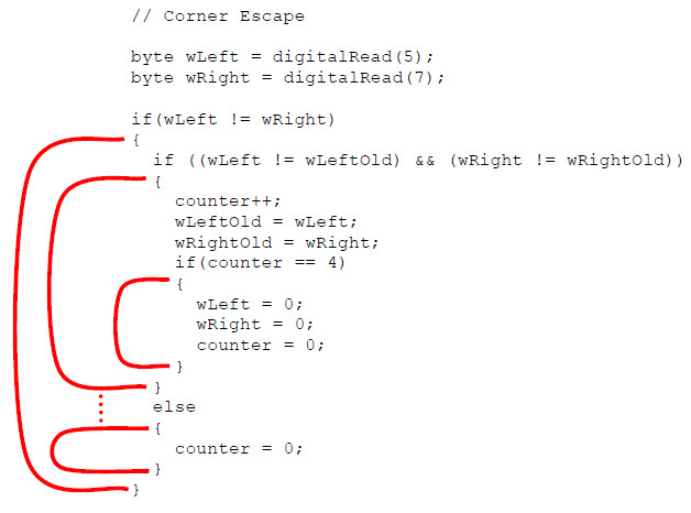
In this picture, the if(wLeft != wRight) statement’s code block contains all the rest of the decision-making code. If it turns out that wLeft is equal to wRight, the Arduino skips to whatever code follows that last closing brace }. The second level if statement compares the old and new wLeft and wRight values with if ((wLeft != wLeftOld) && (wRight != wRightOld)). Notice that its code block ending brace is just below the one for the if(counter==4) block. The if ((wLeft != wLeftOld) && (wRight != wRightOld)) statement also has an else condition with a block that sets counter to zero if the whisker values are not opposite from those of the previous contact.
One of the if statements in EscapingCorners checks to see if counter has reached 4.
This chapter introduced the first sensor system for the BOE Shield-Bot, and allowed the robot to roam around on its own and navigate by touch. The project built on skills acquired in the last chapter, and employed a variety of new ones:
// Robotics with the BOE Shield Chapter 5, Exercise 1
// Value from 0 to 3 indicates whisker states:
// 0 = both, 1 = left, 2 = right, 3 = neither.

void setup()                       // Built-in initialization block
{
  tone(4, 3000, 1000);             // Play tone for 1 second
  delay(1000);                     // Delay to finish tone

  pinMode(7, INPUT);               // Set right whisker pin to input
  pinMode(5, INPUT);               // Set left whisker pin to input

  Serial.begin(9600);              // Set data rate to 9600 bps
}

void loop()                        // Main loop auto-repeats
{
  byte whiskers = 2 * digitalRead(5);
  whiskers += digitalRead(7);

  Serial.println(whiskers);        // Display wLeft

  delay(50);                       // Pause for 50 ms
}
void loop()                             // Main loop auto-repeats
{
  byte wLeft = digitalRead(5);          // Copy right result to wLeft
  byte wRight = digitalRead(7);         // Copy left result to wRight

  if((wLeft == 0) && (wRight == 0))     // If both whiskers contact
  {
    pause(500);                         // Pause motion for 0.5 seconds
    backward(1000);                     // Back up 1 second
    turnLeft(800);                      // Turn left about 120 degrees
  }
  else if(wLeft == 0)                   // If only left whisker contact
  {
    pause(500);                         // Pause motion for 0.5 seconds
    backward(1000);                     // Back up 1 second
    turnRight(400);                     // Turn right about 60 degrees
  }
  else if(wRight == 0)                  // If only right whisker contact
  {
    pause(500);                         // Pause motion for 0.5 seconds
    backward(1000);                     // Back up 1 second
    turnLeft(400);                      // Turn left about 60 degrees
  }
  else                                  // Otherwise, no whisker contact
  {
    forward(20);                        // Forward 1/50 of a second
  }
}
void pause(int time)                    // Pause drive wheels
{
  servoLeft.writeMicroseconds(1500);    // Left wheel stay still
  servoRight.writeMicroseconds(1500);   // Right wheel stay still
  delay(time);                          // Maneuver for time ms
}
void loop()                             // Main loop auto-repeats
{
  byte wLeft = digitalRead(5);          // Copy right result to wLeft
  byte wRight = digitalRead(7);         // Copy left result to wRight

  if((wLeft == 0) && (wRight == 0))     // If both whiskers contact
  {
    pause(500);                         // Pause motion for 0.5 seconds
    backward(1000);                     // Back up 1 second
    turnLeft(800);                      // Turn left about 120 degrees
  }
  else if(wLeft == 0)                   // If only left whisker contact
  {
    pause(500);                         // Pause motion for 0.5 seconds
    backward(1000);                     // Back up 1 second
    turnRight(400);                     // Turn right about 60 degrees
  }
  else if(wRight == 0)                  // If only right whisker contact
  {
    pause(500);                         // Pause motion for 0.5 seconds
    backward(1000);                     // Back up 1 second
    turnLeft(400);                      // Turn left about 60 degrees
  }
  else                                  // Otherwise, no whisker contact
  {
    forward(20);                        // Forward 1/50 of a second
  }
}
// RoamingWithWhiskers  Chapter 5 Project 1
// Go forward.  Back up and turn if whiskers indicate BOE Shield bot
// bumped into something.

#include <Servo.h>                      // Include servo library

Servo servoLeft;                        // Declare left and right servos
Servo servoRight;

void setup()                            // Built-in initialization block
{
  pinMode(7, INPUT);                    // Set right whisker pin to input
  pinMode(5, INPUT);                    // Set left whisker pin to input

  tone(4, 3000, 1000);                  // Play tone for 1 second
  delay(1000);                          // Delay to finish tone

  servoLeft.attach(13);                 // Attach left signal to pin 13
  servoRight.attach(12);                // Attach right signal to pin 12
}

void loop()                             // Main loop auto-repeats
{
  byte wLeft = digitalRead(5);          // Copy right result to wLeft
  byte wRight = digitalRead(7);         // Copy left result to wRight

  if((wLeft == 0) && (wRight == 0))     // If both whiskers contact
  {
    tone(4, 4000, 100);                 // Play a 0.1 ms tone
    pause(200);                         // Stop for 0.2 seconds
    tone(4, 4000, 100);                 // Play a 0.1 ms tone
    pause(200);                         // Stop for 0.2 seconds
    backward(1000);                     // Back up 1 second
    turnLeft(800);                      // Turn left about 120 degrees
  }
  else if(wLeft == 0)                   // If only left whisker contact
  {
    tone(4, 4000, 100);                 // Play a 0.1 ms tone
    pause(200);                         // Stop for 0.2 seconds
    backward(1000);                     // Back up 1 second
    turnRight(400);                     // Turn right about 60 degrees
  }
  else if(wRight == 0)                  // If only right whisker contact
  {
    tone(4, 4000, 100);                 // Play a 0.1 ms tone
    pause(200);                         // Stop for 0.2 seconds
    backward(1000);                     // Back up 1 second
    turnLeft(400);                      // Turn left about 60 degrees
  }
  else                                      // Otherwise, no whisker contact
  {
    forward(20);                            // Forward 1/50 of a second
  }
}

void pause(int time)                        // Backward function
{
  servoLeft.writeMicroseconds(1500);        // Left wheel clockwise
  servoRight.writeMicroseconds(1500);       // Right wheel counterclockwise
  delay(time);                              // Maneuver for time ms
}

void forward(int time)                      // Forward function
{
  servoLeft.writeMicroseconds(1700);        // Left wheel counterclockwise
  servoRight.writeMicroseconds(1300);       // Right wheel clockwise
  delay(time);                              // Maneuver for time ms
}

void turnLeft(int time)                     // Left turn function
{
  servoLeft.writeMicroseconds(1300);        // Left wheel clockwise
  servoRight.writeMicroseconds(1300);       // Right wheel clockwise
  delay(time);                              // Maneuver for time ms
}

void turnRight(int time)                    // Right turn function
{
  servoLeft.writeMicroseconds(1700);        // Left wheel counterclockwise
  servoRight.writeMicroseconds(1700);       // Right wheel counterclockwise
  delay(time);                              // Maneuver for time ms
}

void backward(int time)                     // Backward function
{
  servoLeft.writeMicroseconds(1300);    // Left wheel clockwise
  servoRight.writeMicroseconds(1700);   // Right wheel counterclockwise
  delay(time);                          // Maneuver for time ms
}
// Robotics with the BOE Shield - Chapter 5, project 2 – WhiskerCircle
// BOE Shield-Bot navigates a circle of 1 yard diameter.
// Tightens turn if right whisker pressed, or reduces turn if left whisker
// is pressed.

#include <Servo.h>                    // Include servo library

Servo servoLeft;                      // Declare left and right servos
Servo servoRight;

int turn;

void setup()                          // Built-in initialization block
{
  pinMode(7, INPUT);                    // Set right whisker pin to input
  pinMode(5, INPUT);                    // Set left whisker pin to input

  tone(4, 3000, 1000);                // Play tone for 1 second
  delay(1000);                        // Delay to finish tone

  servoLeft.attach(13);               // Attach left signal to Port 13
  servoRight.attach(12);              // Attach right signal to Port 12

  turn = 0;

//  servoLeft.detach();                 // Stop sending servo signals
//  servoRight.detach();
}

void loop()                          // Main loop auto-repeats
{                                    // Nothing needs repeating
  int wLeft = digitalRead(5);
  int wRight = digitalRead(7);

  if(wLeft == 0)
  {
    turn -= 10;
  }
  else if(wRight == 0)
  {
    turn += 10;
  }

  // Arc to the right
  servoLeft.writeMicroseconds(1600);  // Left wheel counterclockwise
  servoRight.writeMicroseconds(1438 + turn); // Right wheel clockwise slower
  delay(50);                       // ...for 25.5 seconds
}
Light sensors have many applications in robotics and industrial control: finding the edge of a roll of fabric in a textile mill, determining when to activate streetlights at different times of the year, when to take a picture, or when to deliver water to a crop of plants.
The light sensors in your Robotics Shield Kit respond to visible light, and also to an invisible type of light called infrared. These sensors can be used in different circuits that the Arduino can monitor to detect variations in light level. With this information, your sketch can be expanded to make the BOE Shield-Bot navigate by light, such as driving toward a flashlight beam or an open doorway letting light into a dark room.

A transistor is like a valve that regulates the amount of electric current that passes through two of its three terminals. The third terminal controls just how much current passes through the other two. Depending on the type of transistor, the current flow can be controlled by voltage, current, or in the case of the phototransistor, by light.
The drawing below shows the schematic and part drawing of the phototransistor in your Robotics Shield Kit. The brightness of the light shining on the phototransistor’s base (B) terminal determines how much current it will allow to pass into its collector (C) terminal, and out through its emitter (E) terminal. Brighter light results in more current; less-bright light results in less current.
![]()
The phototransistor looks a little bit like an LED. The two devices do have two similarities. First, if you connect the phototransistor in the circuit backwards, it won’t work right. Second, it also has two different length pins and a flat spot on its plastic case for identifying its terminals. The longer of the two pins indicates the phototransistor’s collector terminal. The shorter pin indicates the emitter, and it connects closer to a flat spot on the phototransistor’s clear plastic case.
In the ocean, you can measure the distance between the peaks of two adjacent waves in feet or meters. With light, which also travels in waves, the distance between adjacent peaks is measured in nanometers (nm) which are billionths of meters. The figure below shows the wavelengths for colors of light we are familiar with, along with some the human eye cannot detect, such as ultraviolet and infrared.
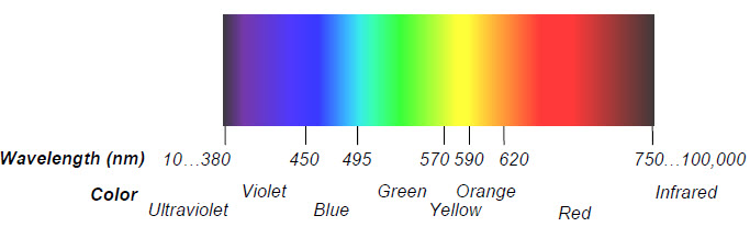
The phototransistor in the Robotics Shield Kit is most sensitive to 850 nm wavelengths, which is in the infrared range. Infrared light is not visible to the human eye, but many different light sources emit considerable amounts of it, including halogen and incandescent lamps and especially the sun. This phototransistor also responds to visible light, though it’s less sensitive, especially to wavelengths below 450 nm.
The phototransistor circuits in this chapter are designed to work well indoors, with fluorescent or incandescent lighting. Make sure to avoid direct sunlight and direct halogen lights; they would flood the phototransistors with too much infrared light.
Imagine that your BOE Shield-Bot is navigating a course, and there’s a bright light at the end. Your robot’s final task in the course is to stop underneath that bright light. There’s a simple phototransistor circuit you can use that lets the Arduino know it detected bright light with a binary‑1, or ambient light with a binary-0. Incandescent bulbs in desk lamps and flashlights make the best bright-light sources. Compact fluorescent and LED light sources are not as easy for the circuit in this activity to recognize.
Ambient means ‘existing or present on all sides’ according to Merriam Webster’s dictionary. For the light level in a room, think about ambient light as the overall level of brightness.
(1) phototransistor
(2) jumper wires
(1) resistor, 2 kΩ (red-black-red)
(1) incandescent or fluorescent flashlight or desk lamp
After some testing, and depending on the light conditions in your robotics area, you might end up replacing the 2 kΩ resistor with one of these resistors, so keep them handy:
(1) resistor, 220 Ω (red-red-brown)
(1) resistor, 470 Ω (yellow-violet-brown)
(1) resistor, 1 kΩ (brown-black-red)
(1) resistor, 4.7 kΩ (yellow-violet-red)
(1) resistor, 10 kΩ (brown-black-orange)
The drawing below will help you tell apart the phototransistor and infrared LED, since they look similar.
The schematic and wiring diagram below show the schematic and wiring diagram of a circuit very similar to the ones in streetlights that turn on automatically at night. The circuit outputs a voltage that varies depending on how much light shines on the phototransistor. The Arduino will monitor the voltage level with one of its analog input pins.
The PhototransistorVoltage sketch makes the Serial Monitor display the voltage measured at A3—one of the Arduino’s five analog input channels that are accessible through the BOE Shield. In the circuit you just built, a wire connects A3 to the row where the phototransistor’s emitter and resistor meet. The voltage at this part of the circuit will change as the light level sensed by the phototransistor changes. The Serial Monitor screencapture below shows some example voltage measurements.
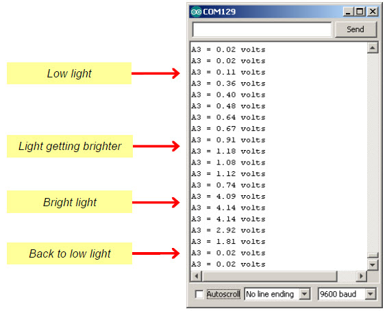
/*
 * Robotics with the BOE Shield - PhototransistorVoltage
 * Display voltage of phototransistor circuit output connected to A3 in
 * the serial monitor.
 */

void setup()                                 // Built-in initialization block
{
  Serial.begin(9600);                        // Set data rate to 9600 bps
}

void loop()                                  // Main loop auto-repeats
{
  Serial.print("A3 = ");                     // Display "A3 = "
  Serial.print(volts(A3));                    // Display measured A3 volts
  Serial.println(" volts");                  // Display " volts" & newline
  delay(1000);                               // Delay for 1 second
}

float volts(int adPin)                       // Measures volts at adPin
{                                            // Returns floating point voltage
 return float(analogRead(adPin)) * 5.0 / 1024.0;
}
The sketch HaltUnderBrightLight will make the BOE Shield-Bot go forward until the phototransistor detects light that’s bright enough to make the voltage applied to A3 exceed 3.5 V. You can change the 3.5 V value to one that’s halfway between the high and low voltage values you recorded from the last sketch.
/*
 * Robotics with the BOE Shield - HaltUnderBrightLight
 * Display voltage of phototransistor circuit output connected to A3 in
 * the serial monitor.
 */

#include <Servo.h>                           // Include servo library

Servo servoLeft;                             // Declare left and right servos
Servo servoRight;

void setup()                                 // Built-in initialization block
{
  tone(4, 3000, 1000);                       // Play tone for 1 second
  delay(1000);                               // Delay to finish tone

  servoLeft.attach(13);                      // Attach left signal to pin 13
  servoRight.attach(12);                     // Attach right signal to pin 12

  servoLeft.writeMicroseconds(1700);         // Full speed forward
  servoRight.writeMicroseconds(1300);
}

void loop()                                  // Main loop auto-repeats
{
  if(volts(A3) > 3.5)                        // If A3 voltage greater than 3.5
  {
    servoLeft.detach();                      // Stop servo signals
    servoRight.detach();
  }
}

float volts(int adPin)                       // Measures volts at adPin
{                                            // Returns floating point voltage
 return float(analogRead(adPin)) * 5.0 / 1024.0;
}
The Arduino’s A0, A1…A5 sockets are connected to Atmel microcontroller pins that are configured for analog to digital conversion. It’s how microcontrollers measure voltage: they split a voltage range into many numbers, with each number representing a voltage. Each of the Arduino’s analog inputs has a 10-bit resolution, meaning that it uses 10 binary digits to describe its voltage measurement. With 10 binary digits, you can count from 0 to 1023; that’s a total of 1024 voltage levels if you include zero.
By default, the Arduino’s analogRead function is configured to use the 0…1023 values to describe where a voltage measurement falls in a 5 V scale. If you split 5 V into 1024 different levels, each level is 5/1024ths of a volt apart. 5/1024ths of a volt is approximately 0.004882813 V, or about 4.89 thousandths of a volt. So, to convert a value returned by analogRead to a voltmeter-style value, all the volts function has to do is multiply by 5 and divide by 1024.
Example:
The analogRead function returns 645; how many volts is that?
Answer:
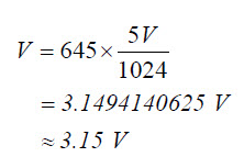
The sketches have been calling the volts function with volts(A3). When they do that, they pass A3 to its adPin parameter. Inside the function, analogRead(adPin) becomes analogRead(A3). It returns a value in the 0 to 1023 range that represents the voltage applied to A3. The analogRead call returns an integer, but since it is nested in float(analogRead(adPin), that integer value gets converted to floating point. Then, it’s multiplied by the floating point value 5.0 and divided by 1024.0, which converts it to a voltmeter value (just like we converted 645 to 3.15 V).
float volts(int adPin)                       // Measures volts at adPin
{                                            // Returns floating point voltage
 return float(analogRead(adPin)) * 5.0 / 1024.0;
}
Since return is to the left of the calculation in the volts function block, the result gets returned to the function call. The sketch PhototransistorVoltage displays the value returned by the volts function with Serial.print(volts(A3)).
HaltUnderBrightLight uses that vaule in the if(volts(A3) > 3.5) expression to bring the BOE Shield-Bot to a halt under the light.
Binary vs. Analog and Digital
A binary sensor can transmit two different states, typically to indicate the presence or absence of something. For example, a whisker sends a high signal if it is not pressed, or a low signal if it is pressed.
An analog sensor sends a continuous range of values that correspond to a continuous range of measurements. The phototransistor circuits in this activity are examples of analog sensors. They provide continuous ranges of values that correspond to continuous ranges of light levels.
A digital value is a number expressed by digits. Computers and microcontrollers store analog measurements as digital values. The process of measuring an analog sensor and storing that measurement as a digital value is called analog to digital conversion. The measurement is called a digitized measurement. Analog to digital conversion documents will also call them quantized measurements.
The Ardunio’s map Function
In the PhototransistorVoltage sketch, we converted measurements from the 0 to 1023 range to the 0.0 to 4.995 volt range for display. For other applications, you might need to convert the value to some other range of integers so that your sketch can pass it to another function, maybe for motor control, or maybe for more analysis.
That’s where the Ardunio’s map function comes in handy. It’s useful for “mapping” a value in one range of integers to an equivalent value in some other range. For example, let’s say you want to map a measurement in the 0 to 1024 range to a range of 1300 to 1700 for servo control. Here is an example of how you could use the map function to do it:
int adcVal = analogRead(A3);
int newAdcVal = map(adcVal, 0, 1023, 1300, 1700);
In this example, if the value of adcVal is 512 , the result of the map function for the newAdcVal call would be 1500 . So, the measurement got mapped from a point about half way through the 0..1023 range to its equivalent point in the 1300…1700 range.
A resistor “resists” the flow of current. Voltage in a circuit with a resistor can be likened to water pressure. For a given amount of electric current, more voltage (pressure) is lost across a larger resistor than a smaller resistor that has the same amount of current passing through it. If you instead keep the resistance constant and vary the current, you can measure a larger voltage (pressure drop) across the same resistor with more current, or less voltage with less current.
The Arduino’s analog inputs are invisible to the phototransistor circuit. So, A3 monitors the circuit but has no effect on it. Take a look at the circuit below. With 5 volts (5 V) at the top and GND (0 V) at the bottom of the circuit, 5 V of electrical pressure (voltage) makes the supply of electrons in the BOE Shield-Bot’s batteries want to flow through it.
The reason the voltage at A3 (VA3) changes with light is because the phototransistor lets more current pass when more light shines on it, or less current pass with less light. That current, which is labeled I in the circuit below, also has to pass through the resistor. When more current passes through a resistor, the voltage across it will be higher. When less current passes, the voltage will be lower. Since one end of the resistor is tied to Vss = 0 V, the voltage at the VA3 end goes up with more current and down with less current.
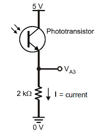
If you replace the 2 kΩ resistor with a 1 kΩ resistor, VA3 will see smaller values for the same currents. In fact, it will take twice as much current to get VA3 to the same voltage level, which means the light will have to be twice as bright to reach the 3.5 V level, the default voltage in HaltUnderBrightLight to make the BOE Shield-Bot stop.
So, a smaller resistor in series with the phototransistor makes the circuit less sensitive to light. If you instead replace the 2 kΩ resistor with a 10 kΩ resistor, VA3 will be 5 times larger with the same current, and it’ll only take 1/5th the light to generate 1/5th the current to get VA3 past the 3.5 V level. So, a larger resistor makes the circuit more sensitive to light.
Connected in Series When two or more elements are connected end-to-end, they are connected in series. The phototransistor and resistor in this circuit are connected in series.
Two properties affect the voltage at VA3: current and resistance, and Ohm’s Law explains how it works. Ohm’s Law states that the voltage (V) across a resistor is equal to the current (I) passing through it multiplied by its resistance (R). So, if you know two of these values, you can use the Ohm’s Law equation to calculate the third:
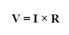
In some textbooks, you will see E = I × R instead. E stands for electric potential, which is another way to say “volts.”
Voltage (V) is measured in units of volts, which are abbreviated with an upper-case V. Current (I) is measured in amperes, or amps, which are abbreviated A. Resistance (R) is measured in ohms which is abbreviated with the Greek letter omega (Ω). The current levels you are likely to see through this circuit are in milliamps (mA). The lower-case m indicates that it’s a measurement of thousandths of amps. Similarly, the lower-case k in kΩ indicates that the measurement is in thousands of ohms.
Let’s use Ohm’s Law to calculate VA3 in with the phototransistor, letting two different amounts of current flow through the circuit:
The examples below show the conditions and their solutions. When you try these calculations, remember that milli (m) is thousandths and kilo (k) is thousands when you substitute the numbers into Ohm’s Law.
Example 1: I = 1.75 mA and R = 2 kΩ
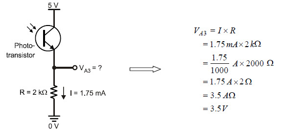
Example 2: 1 = 0.25 mA and R = 2 kΩ
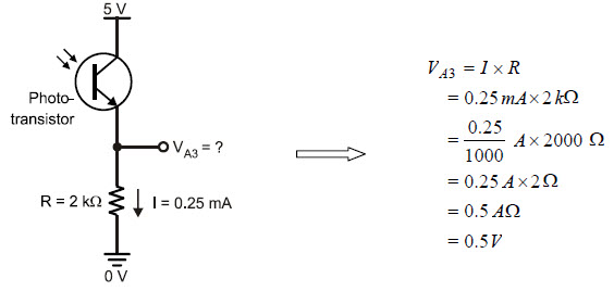
Let’s say that the ambient light in your room is twice as bright as the light that resulted in VA3 = 3.5 V for bright light and 0.5 V for shade. Another situation that could cause higher current is if the ambient light is a stronger source of infrared. In either case, the phototransistor could allow twice as much current to flow through the circuit, which could lead to measurement difficulties.
Question: What could you do to bring the circuit’s voltage response back down to 3.5 V for bright light and 0.5 V for dim?
Answer: Cut the resistor value in half; make it 1 kΩ instead of 2 kΩ.
The circuit in the previous activity only works over a limited light range. You might get the Activity #1 circuit all nice and calibrated in one room, then take it to a brighter room and find that all the voltage measurements will sit at the maximum value. Or, maybe you’ll take it into a darker room, and the voltages will end up never making it past 0.1 V.
This activity introduces a different phototransistor circuit that the Arduino can use to measure a much wider range of light levels. This circuit and sketch can return values ranging from 0 to over 75,000. Be aware: this time the smaller values indicate bright light, and large values indicate low light.
A capacitor is a device that stores charge, and it is a fundamental building block of many circuits. Batteries are also devices that store charge, and for these activities it will be convenient to think of capacitors as tiny batteries that can be charged, discharged, and recharged.
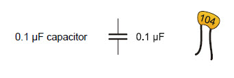
How much charge a capacitor can store is measured in farads (F). A farad is a very large value that’s not practical for use with these BOE Shield-Bot circuits. The capacitors in your kit store fractions of millionths of farads. A millionth of a farad is called a microfarad, and it is abbreviated μF. This one stores one tenth of one millionth of a farad: 0.1 μF.
microfarads: (millionths of a farad), abbreviated μF 1 μF = 1×10⁻⁶ F
nanofarads: (billionths of a farad), abbreviated nF 1 nF = 1×10⁻⁹ F
picofarads: (trillionths of a farad), abbreviated pF 1 pF = 1×10-12 F
The 104 on the 0.1 μF capacitor’s case is a measurement in picofarads or (pF). In this labeling system, 104 is the number 10 with four zeros added, so the capacitor is 100,000 pF, which is 0.1 μF.
(100,000) × (1 × 10-12) F = (100 × 103) × (1 × 10-12) F
= 100 × 10-9 F = 0.1 × 10⁻⁶ F
= 0.1 μF.
These circuits can respond independently to the light level reaching each phototransistor. They will be pointing upward at about 45°, one forward-left and the other forward-right. This way, a sketch monitoring the values of both phototransistors can determine which side of the BOE Shield-Bot sees brighter light. Then, this information can be used for navigation decisions.
(2) phototransistors
(2) capacitors, 0.1 μF (104)
(2) resistors, 1 kΩ (brown-black-red)
(2) jumper wires
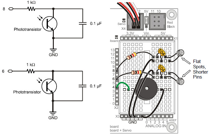
The roaming examples in this chapter will depend on the phototransistors being pointed upward and outward to detect differences in light levels from different directions.
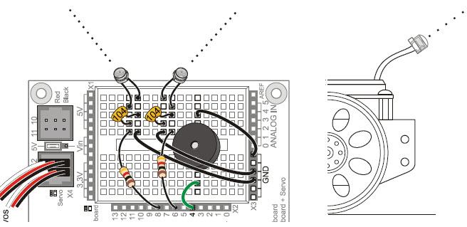
Think of each capacitor in this circuit as a tiny rechargeable battery, and think of each phototransistor as a light-controlled current valve. Each capacitor can be charged to 5 V and then allowed to drain through its phototransistor. The rate that the capacitor loses its charge depends on how much current the phototransistor (current valve) allows to pass, which in turn depends on the brightness of the light shining on the phototransistor’s base. Again, brighter light results in more current passing, shadows result in less current.
This kind of phototransistor/capacitor circuit is called a charge transfer circuit. The Arduino will determine the rate at which each capacitor loses its charge through its phototransistor by measuring how long it takes the capacitor’s voltage to decay, that is, to drop below a certain voltage value. The decay time corresponds to how wide open that current valve is, which is controlled by the brightness of the light reaching the phototransistor’s base. More light means faster decay, less light means slower decay.
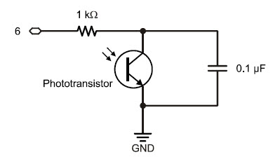
QT Circuit: A common abbreviation for charge transfer is QT. The letter Q refers to electrical charge (an accumulation of electrons), and T is for transfer.
Connected in Parallel: The phototransistor and capacitor shown in Figure 6‑11 are connected in parallel; each of their leads are connected to common terminals (also called nodes). The phototransistor and the capacitor each have one lead connected to GND, and they also each have one lead connected to the same 1 kΩ resistor lead.
The sketch LeftLightSensor charges the capacitor in the pin 8 QT circuit, measures the voltage decay time, and displays it in the Serial Monitor. Remember, with this circuit and sketch, lower numbers mean brighter light.
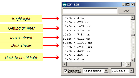
We’ll be using this light-sensing technique for the rest of the chapter, so you can take the BOE Shield-Bot from one room to another without having to worry about finding the right resistors for different ambient light levels.
/*
 * Robotics with the BOE Shield - LeftLightSensor
 * Measures and displays microsecond decay time for left light sensor.
 */

void setup()                                 // Built-in initialization block
{
  tone(4, 3000, 1000);                       // Play tone for 1 second
  delay(1000);                               // Delay to finish tone

  Serial.begin(9600);                        // Set data rate to 9600 bps
}

void loop()                                  // Main loop auto-repeats
{
  long tLeft = rcTime(8);                    // Left rcTime -> tLeft

  Serial.print("tLeft = ");                  // Display tLeft label
  Serial.print(tLeft);                       // Display tLeft value
  Serial.println(" us");                     // Display tLeft units + newline

  delay(1000);                               // 1 second delay
}
                                             // rcTime function at pin
long rcTime(int pin)                         // ..returns decay time
{
  pinMode(pin, OUTPUT);                      // Charge capacitor
  digitalWrite(pin, HIGH);                   // ..by setting pin ouput-high
  delay(1);                                  // ..for 5 ms
  pinMode(pin, INPUT);                       // Set pin to input
  digitalWrite(pin, LOW);                    // ..with no pullup
  long time  = micros();                     // Mark the time
  while(digitalRead(pin));                   // Wait for voltage < threshold
  time = micros() - time;                    // Calculate decay time
  return time;                               // Return decay time
}
Before moving on to navigation, you’ll need to run the same test on the right (pin 6) light sensor circuit. Both circuits have to be working well before you can move on to using them for navigation—there’s that subsystem testing again!
It would also be nice to have a third sketch that tests both phototransistor circuits.
void loop()                                  // Main loop auto-repeats
{
  long tLeft = rcTime(8);                    // Left rcTime -> tLeft
  Serial.print("tLeft = ");                  // Display tLeft label
  Serial.print(tLeft);                       // Display tLeft value
  Serial.print(" us      ");                 // Display tLeft units

  long tRight = rcTime(6);                   // Left rcTime -> tRight
  Serial.print("tRight = ");                 // Display tRight label
  Serial.print(tRight);                      // Display tRight value
  Serial.println(" us");                     // Display tRight units + newline

  delay(1000);                               // 1 second delay
}
When light levels are low, the rcTime function might take time measurements too large for int or even word variables to store. The next step up in storage capacity is a long variable, which can store values from -2,147,483,648 to 2,147,483,647. So, the function definition long rcTime(int pin) is set up to make the function return a long value when it’s done. It also needs to know which pin to measure.
long rcTime(int pin)
A charge transfer measurement takes seven steps: (1) Set the I/O pin high to charge the capacitor. (2) Wait long enough for the capacitor to charge. (3) Change the I/O pin to input. (4) Check the time. (5) Wait for the voltage to decay and pass below the Arduino’s 2.1 V threshold. (6) Check the time again. (7) Subtract the step-3 time from the step-6 time. That’s the amount of time the decay took.
{
  pinMode(pin, OUTPUT);         // Step 1, part 1
  digitalWrite(pin, HIGH);      // Step 1, part 2
  delay(1);                     // Step 2
  pinMode(pin, INPUT);          // Step 3  part 1
  digitalWrite(pin, LOW);       // Step 3, part 2
  long time  = micros();        // Step 4
  while(digitalRead(pin));      // Step 5
  time = micros() - time;       // Step 6 & 7
  return time;
}
In this sketch, Step 1 has two sub-steps. First, pinMode(pin, OUPUT) sets the I/O pin to an output, then digitalWrite(pin, HIGH) makes it supply 5 V to the circuit. Step 3 also has two sub-steps, because the I/O pin is sending a high signal. When the sketch changes the I/O pin’s direction from output-high to input, it adds 10 kΩ of resistance to the circuit, which must be removed. Adding digitalWrite(pin, LOW) after pinMode(pin, INPUT) removes that resistance and allows the capacitor to drain its charge normally through the phototransistor.
The graph below shows the BOE Shield-Bot’s left and right QT circuit voltage responses while the BothLightSensors sketch is running. The device that measures and graphs these voltage responses over time is called an oscilloscope. The two lines that graph the two voltage signals are called traces. The voltage scale for the upper trace is along the left, and the voltage scale for the lower trace is along the right. The time scale for both traces is along the bottom. Labels above each trace show when each command in BothLightSensors executes, so that you can see how the voltage signals respond.
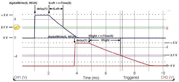
The upper trace in the graph plots the capacitor’s voltage in the pin 8 QT circuit; that’s the left light sensor. In response to digitalWrite(8, HIGH), the voltage quickly rises from 0 V to almost 5 V at about the 1 ms mark. The signal stays at around 5 V for the duration of delay(1). Then, at the 2 ms mark, the rcTime call causes the decay to start. The rcTime function measures the time it takes the voltage to decay to about 2.1 V and stores it in the tLeft variable. In the plot, it looks like that decay took about 1 ms, so the tLeft variable should store a value close to 1000.
The lower trace in the graph plots the pin 6 QT circuit’s capacitor voltage—the right light sensor. This measurement starts after the left sensor measurement is done. The voltage varies in a manner similar to the upper trace, except the decay time takes about 2 ms. We would expect to see tRight store a value in the 2000 neighborhood. This larger value corresponds to a slower decay, which in turn corresponds to a lower light level.
We now have circuits that can work under a variety of lighting conditions. Now we need some code that can adapt as well. An example of sketch code that cannot adapt to change would be:
if(tLeft > 2500)… // Not good for navigation.
Maybe that statement would work well for turning away from shadows in one room, but take it to another with brighter lights, and it might never detect a shadow. Or, take it to a darker room, and it might think it’s seeing shadows all the time. For navigation, what matters is not an actual number reporting the light level over each sensor. What matters is the difference in how much light the two sensors detect, so the robot can turn toward the sensor seeing brighter light (or away from it, depending on what you want.)
The solution is simple. Just divide the right sensor measurement into the sum of both. Your result will always be in the 0 to 1 range. This technique is an example of a normalized differential measurement. Here’s what it looks like as an equation:
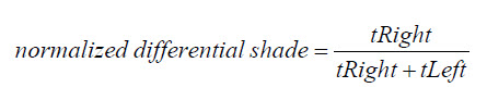
For example, a normalized differential measurement of 0.25 would mean “the light is 1/2 as bright over the right sensor as it is over the left.” The actual values for tRight and tLeft might be small in a bright room or large in a dark room, but the answer will still be 0.25 if the light is 1/2 as bright over the right sensor. A measurement of 0.5 would mean that the tRight and tLeft values are equal. They could both be large, or both be small, but if the result is 0.5, it means the sensors are detecting the same level of brightness.
Here’s another trick: subtract 0.5 from the normalized differential shade measurement. That way, the results range from –0.5 to +0.5 instead of 0 to 1, and a measurement of 0 means equal brightness. The result is a zero-justified normalized differential shade measurement.
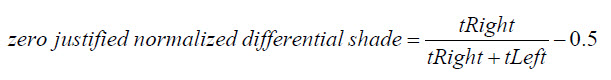
But why do it? The value range –0.5 to +0.5 is great for navigation sketches because the positive and negative values can be used to scale the wheels speeds. Here is how the zero-justified normalized differential shade equation appears in the next sketch:
  float ndShade;                             // Normalized differential shade
  ndShade = tRight / (tLeft + tRight) - 0.5; // Calculate it and subtract 0.5
The final measurement will be stored in a floating point variable named ndShade, so that gets declared first. Then, the next line does the zero-justified normalized differential shade math. The result will be a value in the –0.5 to +0.5 range that represents the fraction of total shade that tRight detects, compared to tLeft. When ndShade is 0, it means tRight and tLeft are the same values, so the sensors are detecting equally bright light. The closer ndShade gets to –0.5, the darker the shade over the right sensor. The closer ndShade gets to 0.5 the darker the shade over the left sensor. This will be very useful for navigation. Let’s test it first with the Serial Monitor.
This screencapture shows a Serial Monitor example with the LightSensorValues sketch running. With shade over the right sensor, the ndShade value is about 0.4. With shade over the left sensor, it’s about –0.4.
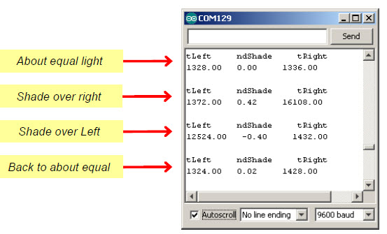
/*
 * Robotics with the BOE Shield - LightSensorValues
 * Displays tLeft, ndShade and tRight in the Serial Monitor.
 */

void setup()                                 // Built-in initialization block
{
  tone(4, 3000, 1000);                       // Play tone for 1 second
  delay(1000);                               // Delay to finish tone

  Serial.begin(9600);                        // Set data rate to 9600 bps
}

void loop()                                  // Main loop auto-repeats
{
  float tLeft = float(rcTime(8));            // Get left light & make float
  float tRight = float(rcTime(6));           // Get right light & make float

  float ndShade;                             // Normalized differential shade
  ndShade = tRight / (tLeft + tRight) - 0.5; // Calculate it and subtract 0.5

  // Display heading
  Serial.println("tLeft     ndShade     tRight");

  Serial.print(tLeft);                       // Display tLeft value
  Serial.print("   ");                       // Display spaces
  Serial.print(ndShade);                     // Display ndShade value
  Serial.print("     ");                     // Display more spaces
  Serial.println(tRight);                    // Display tRight value
  Serial.println(' ');                       // Add an extra newline

  delay(1000);                                // 1 second delay
}

long rcTime(int pin)                         // rcTime measures decay at pin
{
  pinMode(pin, OUTPUT);                      // Charge capacitor
  digitalWrite(pin, HIGH);                   // ..by setting pin ouput-high
  delay(5);                                  // ..for 5 ms
  pinMode(pin, INPUT);                       // Set pin to input
  digitalWrite(pin, LOW);                    // ..with no pullup
  long time  = micros();                     // Mark the time
  while(digitalRead(pin));                   // Wait for voltage < threshold
  time = micros() - time;                    // Calculate decay time
  return time;                               // Returns decay time
}
The Serial Monitor screencapture below shows an example of a graphical display of the ndShade variable. The asterisk will be in the center of the -0.5 to +0.5 scale if the light or shade is the same over both sensors. If the shade is darker over the BOE Shield-Bot’s right sensor, the asterisk will position to the right in the scale. If it’s darker over the left, the asterisk will position toward the left. A larger shade/light contrast (like darker shade over one of the sensors) will result in the asterisk positioning further from the center.
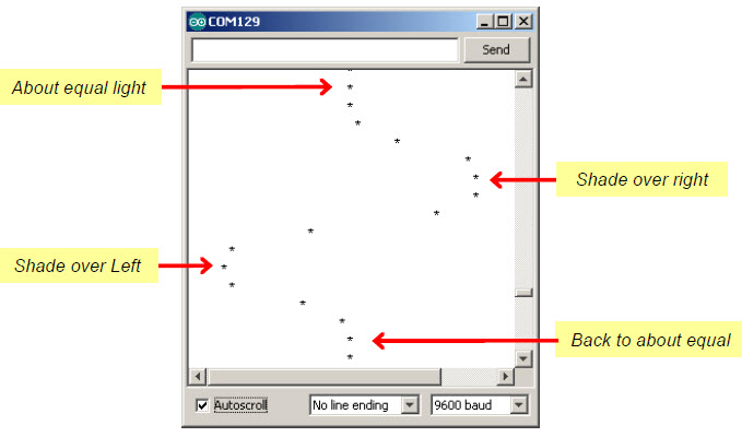
/*
 * Robotics with the BOE Shield - LightSensorDisplay
 * Displays a scrolling graph of ndShade.  The asterisk positions ranges
 * from 0 to 40 with 20 (middle of the display) indicating same light on
 * both sides.
 */

void setup()                                 // Built-in initialization block
{
  tone(4, 3000, 1000);                       // Play tone for 1 second
  delay(1000);                               // Delay to finish tone

  Serial.begin(9600);                        // Set data rate to 9600 bps
}

void loop()                                  // Main loop auto-repeats
{
  float tLeft = float(rcTime(8));            // Get left light & make float
  float tRight = float(rcTime(6));           // Get right light & make float

  float ndShade;                             // Normalized differential shade
  ndShade = tRight / (tLeft+tRight) - 0.5;   // Calculate it and subtract 0.5

  for(int i = 0; i<(ndShade * 40) + 20; i++) // Place asterisk in 0 to 40
  {
    Serial.print(' ');                       // Pad (ndShade * 40) + 20 spaces
  }
  Serial.println('*');                       // Print asterisk and newline

  delay(100);                                // 0.1 second delay
}

long rcTime(int pin)                         // rcTime measures decay at pin
{
  pinMode(pin, OUTPUT);                      // Charge capacitor
  digitalWrite(pin, HIGH);                   // ..by setting pin ouput-high
  delay(5);                                  // ..for 5 ms
  pinMode(pin, INPUT);                       // Set pin to input
  digitalWrite(pin, LOW);                    // ..with no pullup
  long time  = micros();                     // Mark the time
  while(digitalRead(pin));                   // Wait for voltage < threshold
  time = micros() - time;                    // Calculate decay time
  return time;                               // Returns decay time
}
The loop function starts by taking the two rcTime measurements for the left and right light sensors, and stores them in tLeft and tRight.
void loop()                                  // Main loop auto-repeats
{
  float tLeft = float(rcTime(8));            // Get left light & make float
  float tRight = float(rcTime(6));           // Get right light & make float
After declaring ndShade as a floating-point variable, tLeft and tRight are used in an expression to get that zero-justified normalized differential measurement. The result will be between –0.5 and +0.5, and gets stored in ndShade.
  float ndShade;                             // Normalized differential shade
  ndShade = tRight / (tLeft+tRight) - 0.5;   // Calculate it and subtract 0.5
Next, this for loop places the cursor in the right place for printing an asterisk. Take a close look at the for loop’s condition. It takes ndShade and multiples it by 40. It also has to add 20 to the value because if ndShade is –0.5, we want that to print with zero leading spaces. So (–0.5 × 40) + 20 = 0. Now, if ndShade is 0, we want it to print 20 spaces over: (0 × 40) + 20 = 20. If it’s +0.5 we want it to print 40 spaces over: (0.5 × 40) + 20 = 40. Of course, if it’s something in between, like 0.25, we have (0.25 × 40) + 20 = 30. So, it’ll print half way between center and far right.
  for(int i = 0; i<(ndShade * 40) + 20; i++) // Place asterisk in 0 to 40
  {
    Serial.print(' ');                       // Pad (ndShade * 40) + 20 spaces
  }
After printing the spaces, a single asterisk prints on the line. Recall that println prints and also adds a newline so that the next time through the loop, the asterisk will display on the next line.
  Serial.println('*');                       // Print asterisk and newline

  delay(100);                                // 0.1 second delay
}
One approach toward making the Boe-Bot roam toward light sources is to make it turn away from shade. You can use the ndShade variable to make the BOE Shield-Bot turn a little or a lot when the contrast between the light detected on each side is a little or a lot.
Here is an if statement that works well for turning away from shade on the right side of the BOE Shield-Bot. It starts by declaring two int variables, speedLeft and speedRight. They are not declared within the if…else block because other blocks in the loop function will need to check their values too. Next, if(ndShade > 0.0) has a code block that will be executed if shade is detected on the robot’s right side, slowing down the left wheel to make the BOE Shield-Bot turn away from the dark. To do this, ndShade * 1000.0 is subtracted from 200. Before assigning the result to speedLeft, int(200.0–(ndShade×1000.0) converts the answer from a floating point value back to an integer. We’re doing this to make the value compatible with the maneuver function from Chapter 4, which needs an int value.
  int speedLeft, speedRight;                 // Declare speed variables

  if (ndShade > 0.0)                         // Shade on right?
  {                                          // Slow down left wheel
    speedLeft = int(200.0 - (ndShade * 1000.0));
    speedLeft = constrain(speedLeft, -200, 200);
    speedRight = 200;                        // Full speed right wheel
  }
This diagram shows an example of how this works when ndShade is 0.125. The left wheel slows down because 200 – (0.125×1000) = 75. Since linear speed control is in the 100 to –100 range, it puts the wheel at about ¾ of full speed. Meanwhile, on the other side, speedRight is set to 200 for full speed forward.

The larger ndShade is, the more it subtracts from 200. That’s not a problem in this example, but if ndShade were 0.45, it would try to store –250 in the speedLeft variable. Since the speeds we’ll want to pass to the maneuver function need to be in the -200 to 200 range, we’ll use the Arduino’s constrain function to prevent speedLeft from going out of bounds: speedLeft = constrain(speedLeft, –200, 200).
Here is an else statement that works well for turning away from shade on the left. It slows down the right wheel and keeps the left wheel going full speed forward. Notice that it adds (ndShade*1000) to 200. Reason being, this is the else statement for if(ndShade > 0.0), so it will get used when ndShade is equal to or smaller than zero. So, if ndShade is –0.125, speedRight = int(200.0 + (ndShade * 1000.0)) would evaluate to 200 + (–1.25 × 1000) = 200 – 125 = 75. The constrain function is used again, to limit speedRight.
  else                                       // Shade on Left?
  {                                          // Slow down right wheel
    speedRight = int(200.0 + (ndShade * 1000.0));
    speedRight = constrain(speedRight, -200, 200);
    speedLeft = 200;                         // Full speed left wheel
  }
Before actually testing out these navigation decisions, it’s best to take a look at the variable values with the Serial Monitor. So, instead of a call to the maneuver function, first, let’s use some Serial.print calls to see if we got it right.
  Serial.print(speedLeft, DEC);              // Display speedLeft
  Serial.print("   ");                       // Spaces
  Serial.print(ndShade, DEC);                // Display ndShade
  Serial.print("    ");                      // More spaces
  Serial.println(speedRight, DEC);           // Display speedRight

  delay(2000);                               // 1 second delay
}
The print and println calls should result in a display that shows the value of speedLeft in the left column, speedRight in the right column, and ndShade between them. Watch it carefully. The side with brighter light will always display 200 for full-speed-forward, and the other will be slowing down with values less than 200—the darker the shade, the smaller the number.

/*
 * Robotics with the BOE Shield - LightSeekingDisplay
 * Displays speedLeft, ndShade, and speedRight in Serial Monitor. Verifies
 * that wheel speeds respond correctly to left/right light/shade conditions.
 */

void setup()                                 // Built-in initialization block
{
  tone(4, 3000, 1000);                       // Play tone for 1 second
  delay(1000);                               // Delay to finish tone

  Serial.begin(9600);                        // Set data rate to 9600 bps
}

void loop()                                  // Main loop auto-repeats
{
  float tLeft = float(rcTime(8));            // Get left light & make float
  float tRight = float(rcTime(6));           // Get right light & make float

  float ndShade;                             // Normalized differential shade
  ndShade = tRight / (tLeft+tRight) - 0.5;   // Calculate it and subtract 0.5

  int speedLeft, speedRight;                 // Declare speed variables

  if (ndShade > 0.0)                         // Shade on right?
  {                                          // Slow down left wheel
    speedLeft = int(200.0 - (ndShade * 1000.0));
    speedLeft = constrain(speedLeft, -200, 200);
    speedRight = 200;                        // Full speed right wheel
  }
  else                                       // Shade on Left?
  {                                          // Slow down right wheel
    speedRight = int(200.0 + (ndShade * 1000.0));
    speedRight = constrain(speedRight, -200, 200);
    speedLeft = 200;                         // Full speed left wheel
  }

  Serial.print(speedLeft, DEC);              // Display speedLeft
  Serial.print("   ");                       // Spaces
  Serial.print(ndShade, DEC);                // Display ndShade
  Serial.print("    ");                      // More spaces
  Serial.println(speedRight, DEC);           // Display speedRight

  delay(1000);                               // 1 second delay
}

long rcTime(int pin)                         // rcTime measures decay at pin
{
  pinMode(pin, OUTPUT);                      // Charge capacitor
  digitalWrite(pin, HIGH);                   // ..by setting pin ouput-high
  delay(5);                                  // ..for 5 ms
  pinMode(pin, INPUT);                       // Set pin to input
  digitalWrite(pin, LOW);                    // ..with no pullup
  long time  = micros();                     // Mark the time
  while(digitalRead(pin));                   // Wait for voltage < threshold
  time = micros() - time;                    // Calculate decay time
  return time;                               // Returns decay time
}
At this point, the LightSeekingDisplay sketch needs four things to take it from displaying what it’s going to do to actually doing it:
The result is the LightSeekingShieldBot sketch.
/*
 * Robotics with the BOE Shield - LightSeekingShieldBot
 * Roams toward light and away from shade.
 */

#include <Servo.h>                           // Include servo library

Servo servoLeft;                             // Declare left and right servos
Servo servoRight;

void setup()                                 // Built-in initialization block
{
  tone(4, 3000, 1000);                       // Play tone for 1 second
  delay(1000);                               // Delay to finish tone

  servoLeft.attach(13);                      // Attach left signal to pin 13
  servoRight.attach(12);                     // Attach right signal to pin 12
}

void loop()                                  // Main loop auto-repeats
{
  float tLeft = float(rcTime(8));            // Get left light & make float
  float tRight = float(rcTime(6));           // Get right light & make float

  float ndShade;                             // Normalized differential shade
  ndShade = tRight / (tLeft+tRight) - 0.5;   // Calculate it and subtract 0.5

  int speedLeft, speedRight;                 // Declare speed variables

  if (ndShade > 0.0)                         // Shade on right?
  {                                          // Slow down left wheel
    speedLeft = int(200.0 - (ndShade * 1000.0));
    speedLeft = constrain(speedLeft, -200, 200);
    speedRight = 200;                        // Full speed right wheel
  }
  else                                       // Shade on Left?
  {                                          // Slow down right wheel
    speedRight = int(200.0 + (ndShade * 1000.0));
    speedRight = constrain(speedRight, -200, 200);
    speedLeft = 200;                         // Full speed left wheel
  }

  maneuver(speedLeft, speedRight, 20);       // Set wheel speeds
}

long rcTime(int pin)                         // rcTime measures decay at pin
{
  pinMode(pin, OUTPUT);                      // Charge capacitor
  digitalWrite(pin, HIGH);                   // ..by setting pin ouput-high
  delay(5);                                  // ..for 5 ms
  pinMode(pin, INPUT);                       // Set pin to input
  digitalWrite(pin, LOW);                    // ..with no pullup
  long time  = micros();                     // Mark the time
  while(digitalRead(pin));                   // Wait for voltage < threshold
  time = micros() - time;                    // Calculate decay time
  return time;                               // Returns decay time
}

// maneuver function
void maneuver(int speedLeft, int speedRight, int msTime)
{
  servoLeft.writeMicroseconds(1500 + speedLeft);   // Set left servo speed
  servoRight.writeMicroseconds(1500 - speedRight); // Set right servo speed
  if(msTime==-1)                                   // if msTime = -1
  {
    servoLeft.detach();                            // Stop servo signals
    servoRight.detach();
  }
  delay(msTime);                                   // Delay for msTime
}
If you want more sensitivity to light, change 1000 to a larger value in these two commands:
    speedLeft = int(200.0 - (ndShade * 1000.0));
    speedRight = int(200.0 + (ndShade * 1000.0));
Want less light sensitivity? Change 1000 to a smaller value.
Here are several more light-sensing navigation ideas for your BOE Shield-Bot that can be made with adjustments to the loop function:
This chapter focused on using a pair of light sensors to detect bright light and shade for robot navigation. Lots of interesting electronics concepts and programming techniques come into play.
  for(int i = 1; i<=50; i++)  // Repeat 50 times
  {
    Serial.print('=');        // one = char each time through
  }
/*
 * Robotics with the BOE Shield - Chapter 6, Project 1
 * Chirp when light is above threshold.  Will require updating value of
 * threshold & retesting under bright light to get to the right value.
 */

void setup()                         // Built-in initialization block
{
  tone(4, 3000, 1000);               // Play tone for 1 second
  delay(1000);                       // Delay to finish tone
}

void loop()                          // Main loop auto-repeats
{
  if(volts(A3) > 3.5)                 // If A3 voltage greater than 3.5
  {
    tone(4, 4000, 50);               // Start chirping
    delay(100);
  }
}

float volts(int adPin)               // Measures volts at adPin
{                                    // Returns floating point voltage
 return float(analogRead(adPin)) * 5.0 / 1024.0;
}
Next, add an if statement similar to the one from HaltUnderBrightLight to the main loop of LightSeekingShieldBot. Careful though, HaltUnderBrightLight uses the greater than (>) operator because it’s using a voltage output circuit. We need the less than (<) operator for the QT circuit because smaller values mean brighter light. We also need to express the threshold as a floating point value, like 1300.0. Here’s an example:
  // Add this if condition to stop under the bright lamp.
  if((tRight + tLeft) < 1300.0)   // tLeft+tRight < 1300?
  {
    servoLeft.detach();           // Stop servo signals
    servoRight.detach();
  }
Here’s a modified version of LightSeekingShieldBot that will do the trick. Remember, you’ll still have to calibrate it to your lighting conditions.
/*
 * Robotics with the BOE Shield - Chapter 6, Project 3
 * Roams toward light and away from shade.
 */

#include <Servo.h>                           // Include servo library

Servo servoLeft;                             // Declare left and right servos
Servo servoRight;

void setup()                                 // Built-in initialization block
{
  tone(4, 3000, 1000);                       // Play tone for 1 second
  delay(1000);                               // Delay to finish tone

  servoLeft.attach(13);                      // Attach left signal to pin 13
  servoRight.attach(12);                     // Attach right signal to pin 12
}

void loop()                                  // Main loop auto-repeats
{
  float tLeft = float(rcTime(8));            // Get left light & make float
  float tRight = float(rcTime(6));           // Get right light & make float

  // Add this if condition to stop under the bright lamp.
  if((tRight + tLeft) < 1300.0)              // If A3 voltage greater than 2
  {
    servoLeft.detach();                      // Stop servo signals
    servoRight.detach();
  }

  float ndShade;                             // Normalized differential shade
  ndShade = tRight / (tLeft+tRight) - 0.5;   // Calculate it and subtract 0.5

  int speedLeft, speedRight;                 // Declare speed variables

  if (ndShade > 0.0)                         // Shade on right?
  {                                          // Slow down left wheel
    speedLeft = int(200.0 - (ndShade * 1000.0));
    speedLeft = constrain(speedLeft, -200, 200);
    speedRight = 200;                        // Full speed right wheel
  }
  else                                       // Shade on Left?
  {                                          // Slow down right wheel
    speedRight = int(200.0 + (ndShade * 1000.0));
    speedRight = constrain(speedRight, -200, 200);
    speedLeft = 200;                         // Full speed left wheel
  }

  maneuver(speedLeft, speedRight, 20);       // Set wheel speeds
}

long rcTime(int pin)                         // rcTime measures decay at pin
{
  pinMode(pin, OUTPUT);                      // Charge capacitor
  digitalWrite(pin, HIGH);                   // ..by setting pin ouput-high
  delay(5);                                  // ..for 5 ms
  pinMode(pin, INPUT);                       // Set pin to input
  digitalWrite(pin, LOW);                    // ..with no pullup
  long time  = micros();                     // Mark the time
  while(digitalRead(pin));                   // Wait for voltage < threshold
  time = micros() - time;                    // Calculate decay time
  return time;                               // Returns decay time
}

// maneuver function
void maneuver(int speedLeft, int speedRight, int msTime)
{
  servoLeft.writeMicroseconds(1500 + speedLeft);   // Set Left servo speed
  servoRight.writeMicroseconds(1500 - speedRight); // Set right servo speed
  if(msTime==-1)                                   // if msTime = -1
  {
    servoLeft.detach();                            // Stop servo signals
    servoRight.detach();
  }
  delay(msTime);                                   // Delay for msTime
}
The BOE Shield-Bot can already use whiskers to get around, but it only detects obstacles when it bumps into them. Wouldn’t it be better if the BOE Shield-Bot could just “see” objects and then decide what to do about them? Well, that’s what it can do with infrared headlights and eyes like the ones shown below. Each headlight is an infrared LED inside a tube that directs the light forward, just like a flashlight. Each eye is an infrared receiver that sends the Arduino high/low signals to indicate whether it detects the infrared LED’s light reflected off an object.
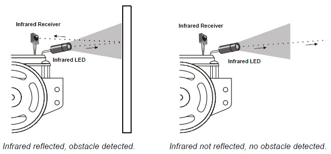
Code Update Notice
The Chapter 7 Arduino Code was updated on 11/15/2012. See the notice on this page for details.
Infrared is abbreviated IR, and it is light the human eye cannot detect (for a refresher, take a look at the visible light spectrum here. The IR LEDs introduced in this chapter emit infrared light, just like the red LEDs we’ve been using emit visible light.
The infrared receivers in this chapter detect infrared light, similar to the phototransistors in the last chapter. But, there’s a difference—these infrared receivers are not just detecting ambient light, but they are designed to detect infrared light flashing on and off very quickly.
The infrared LED that the BOE Shield-Bot will use as a tiny headlight is actually the same one you can find in just about any TV remote. The TV remote flashes the IR LED to send messages to your TV. The microcontroller in your TV picks up those messages with an infrared receiver like the one your BOE Shield-Bot will use.
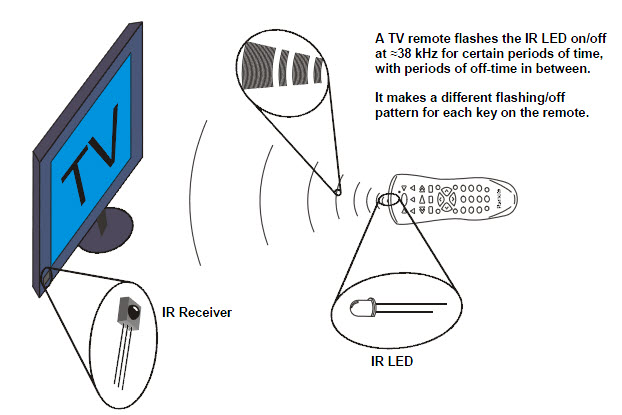
The TV remote sends messages by flashing the IR LED very fast, at a rate of about 38 kHz (about 38,000 times per second). The IR receiver only responds to infrared if it’s flashing at this rate. This prevents infrared from sources like the sun and incandescent lights from being misinterpreted as messages from the remote. So, to send signals that the IR receiver can detect, your Arduino will have to flash the IR LED on/off at 38 kHz.
Some fluorescent lights do generate signals that can be detected by the IR receivers.
These lights can cause problems for your BOE Shield-Bot’s infrared headlights. One of the things you will do in this chapter is develop an infrared interference “sniffer” that you can use to test the fluorescent lights near your BOE Shield-Bot courses.
The light sensors inside most digital cameras, including cell phones and webcams, can all detect infrared light. By looking through a digital camera, we can “see” if an infrared LED is on or off. These photos show an example with a digital camera and a TV remote. When you press and hold a button on the remote and point the IR LED into the digital camera’s lens, it displays the infrared LED as a flashing, bright white light.
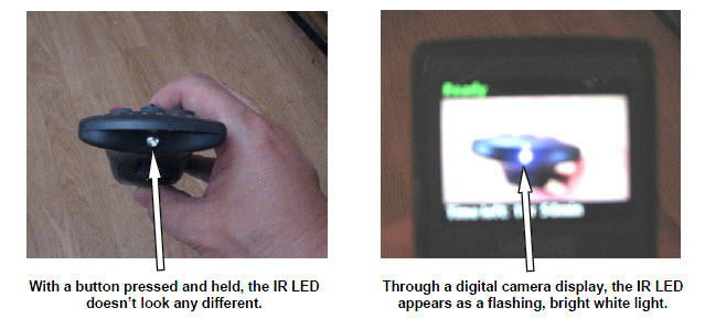
The pixel sensors inside the digital camera detect red, green, and blue light levels, and the processor adds up those levels to determine each pixel’s color and brightness. Regardless of whether a pixel sensor detects red, green, or blue, it detects infrared. Since all three pixel color sensors also detect infrared, the digital camera display mixes all the colors together, which results in white.
Infra means below, so infrared means below red.
The name refers to the fact that the frequency of infrared light waves is less than the frequency of red light waves. The wavelength our IR LED transmits is 980 nanometers (abbreviated nm), and that’s the same wavelength our IR receiver detects. This wavelength is in the near-infrared range. The far-infrared range is 2000 to 10,000 nm, and certain wavelengths in this range are used for night-vision goggles and IR temperature sensing.
In this activity, you will build and test infrared object detectors for the BOE Shield-Bot.
(2) IR receivers
(2) IR LEDs (clear case)
(2) IR LED shield assemblies
(2) Resistors, 220 Ω (red-red-brown)
(2) Resistors, 2 kΩ (red-black-red)
(misc) Jumper wires
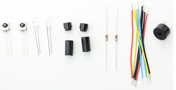
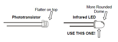
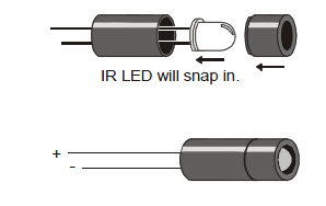
The next figures show the IR object detection schematic wiring diagram. One IR object detector (IR LED and receiver pair) is mounted on each corner of the breadboard closest to the very front of the BOE Shield-Bot.
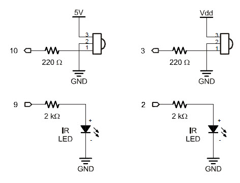
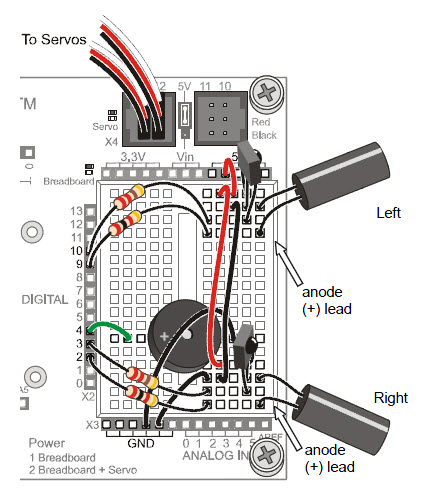
Watch your IR LED anodes and cathodes!
The anode lead is the longer lead on an IR LED by convention. The cathode lead is shorter and mounted in the plastic case closer to its flat spot. These are the same conventions as the red LEDs we have been using.
Your BOE Shield-Bot’s infrared receivers are designed to detect infrared light (in the 980 nanometer range) flashing at a rate near 38 kHz. To make the IR LED turn on/off at that rate, we can use the familiar tone function that makes the speaker beep at the beginning of each sketch.
Infrared detection takes three steps:
Here is an example of the three steps applied to the left IR LED (pin 9) and IR receiver (pin 10).
  tone(9, 38000, 8);                // IRLED 38 kHz for at least 1 ms
  delay(1);                         // Wait 1 ms
  int ir = digitalRead(10);         // IR receiver -> ir variable
The tone actually lasts about 1.1 ms. Even though we would expect tone(9, 38000, 8) to generate a 38 kHz signal for 8 ms, the signal actually only lasts for about 1.1 ms as of Arduino software v1.0. Given the name tone, the function may have been designed for and tested with audible tones. If played on a speaker, a 38 kHz tone will not be audible. It’s in the ultrasonic range, meaning it’s pitch is so high that it’s above the audible range for humans, which is about 20 Hz to 20 kHz.
The tone function generates a square wave that repeats its high/low cycle 38000 times per second. Through experimentation with Arduino software v1.0, the author discovered that a call to tone with a duration of 8 ms resulted in a 38 kHz square wave that lasted about 1.1 ms. .
Remember that the tone function does its processing in the background. Since the IR receiver needs a few tenths of a millisecond to respond to the 38 kHz signal, delay(1) prevents the ir = digitalRead(10) call from copying the IR receiver’s output until it’s ready.
The next sketch defines a function named irDetect with three parameters: one to specifiy the IR LED pin, one to specify the IR receiver pin, and one to set the frequency for flashing the IR LED.
int irDetect(int irLedPin, int irReceiverPin, long frequency)
In the loop function you’ll see a call to irDetect:
int irLeft = irDetect(9, 10, 38000); // Check for object
This call passes 9 to the irLedPin parameter, 10 to irReceiverPin, and 38000 to the frequency parameter. The function performs those three steps for infrared detection and returns 1 if no object is detected, or 0 if an object is detected. That return value gets stored in irLeft.
This sketch only tests the BOE Shield-Bot’s left IR detector. This helps simplify trouble-shooting because you are focusing on only one of the two circuits. This is yet another example of subsystem testing. After the subsystems check out, we can move to system integration. But first, you’ve got to make sure to test and correct any wiring or code entry errors that might have crept in.
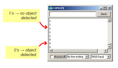
/*
 * Robotics with the BOE Shield - TestLeftIR
 * Display 1 if the left IR detector does not detect an object,
 * or 0 if it does.
 */

void setup()                                 // Built-in initialization block
{
  tone(4, 3000, 1000);                       // Play tone for 1 second
  delay(1000);                               // Delay to finish tone

  pinMode(10, INPUT);  pinMode(9, OUTPUT);   // Left IR LED & Receiver

  Serial.begin(9600);                        // Set data rate to 9600 bps
}

void loop()                                  // Main loop auto-repeats
{
  int irLeft = irDetect(9, 10, 38000);       // Check for object

  Serial.println(irLeft);                    // Display 1/0 no detect/detect

  delay(100);                                // 0.1 second delay
}

// IR Object Detection Function

int irDetect(int irLedPin, int irReceiverPin, long frequency)
{
  tone(irLedPin, frequency, 8);              // IRLED 38 kHz for at least 1 ms
  delay(1);                                  // Wait 1 ms
  int ir = digitalRead(irReceiverPin);       // IR receiver -> ir variable
  delay(1);                                  // Down time before recheck
  return ir;                                 // Return 1 no detect, 0 detect
}
Modifying the sketch to test the right IR object detector is a matter of replacing irLeft with irRight, and passing the correct pin numbers to the irDetect parameters to test the other circuit. Here’s a checklist of the changes:
In this activity, you will build and test indicator LEDs that will tell you if an object is detected without the help of the Serial Monitor. This is handy if you are not near a PC or laptop, and you need to troubleshoot your IR detector circuits.
You will also write a sketch to “sniff” for infrared interference from fluorescent lights. Some fluorescent lights send signals that resemble the signal sent by your infrared LEDs. The device inside a fluorescent light fixture that controls voltage for the lamp is called the ballast. Some ballasts operate in the same frequency range of your IR detector, causing the lamp to emit a 38.5 kHz infrared signal. When using IR object detection for navigation, ballast interference can cause some bizarre BOE Shield-Bot behavior!
LED indicator circuits are similar to the ones you used with the whiskers. Make sure to be careful about your cathodes and anodes when you connect them.
(2) Red LEDs
(2) Resistors, 220 Ω (red-red-brown)
(misc) Jumper wires
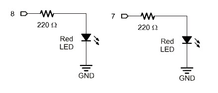
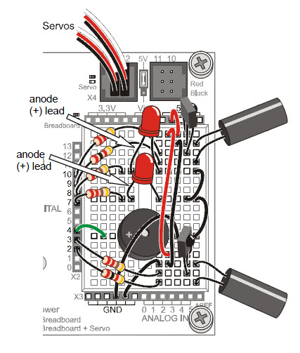
There are quite a few components involved in this system, and this increases the likelihood of a wiring error. That’s why it’s important to have a test sketch that shows you what the infrared detectors are sensing. Use this sketch to verify that all the circuits are working before unplugging the BOE Shield-Bot from its programming cable.
/*
 * Robotics with the BOE Shield – TestBothIrAndInciators
 * Test both IR detection circuits with the Serial Monitor.  Displays 1 if
 * the left IR detector does not detect an object, or 0 if it does.
 * Also displays IR detector states with indicator LEDs.
 */

void setup()                                 // Built-in initialization block
{
  tone(4, 3000, 1000);                       // Play tone for 1 second
  delay(1000);                               // Delay to finish tone

  pinMode(10, INPUT);  pinMode(9, OUTPUT);   // Left IR LED & Receiver
  pinMode(3, INPUT);  pinMode(2, OUTPUT);    // Right IR LED & Receiver
  pinMode(8, OUTPUT); pinMode(7, OUTPUT);    // Indicator LEDs

  Serial.begin(9600);                        // Set data rate to 9600 bps
}

void loop()                                  // Main loop auto-repeats
{
  int irLeft = irDetect(9, 10, 38000);       // Check for object on left
  int irRight = irDetect(2, 3, 38000);       // Check for object on right

  digitalWrite(8, !irLeft);                  // LED states opposite of IR
  digitalWrite(7, !irRight);

  Serial.print(irLeft);                      // Display 1/0 no detect/detect
  Serial.print("  ");                        // Display 1/0 no detect/detect
  Serial.println(irRight);                   // Display 1/0 no detect/detect

  delay(100);                                // 0.1 second delay
}

// IR Object Detection Function

int irDetect(int irLedPin, int irReceiverPin, long frequency)
{
  tone(irLedPin, frequency, 8);              // IRLED 38 kHz for at least 1 ms
  delay(1);                                  // Wait 1 ms
  int ir = digitalRead(irReceiverPin);       // IR receiver -> ir variable
  delay(1);                                  // Down time before recheck
  return ir;                                 // Return 1 no detect, 0 detect
}
After the two calls to the irDetect function, irLeft and irRight each store a 1 if an object is not detected, or 0 if an object is detected. The sketch could have used an if…else statement to turn the indicator lights on/off depending on the value of irLeft and irRight. But, there are other ways!
This approach uses the values of irLeft and irRight directly. There’s only one catch: when (for example) irLeft stores 0, we want its red indicator LED to turn on, and if it stores 1, we want its LED to turn off. Since 1 makes the indicator LED turn on and 0 turns it off, using digitalWrite(8, irLeft) would give us the opposite of what we want. So, the sketch uses the not operator (!) to invert the value that irLeft stores. Now, digitalWrite(8, !irLeft) inverts the value of IrLeft so that when it stores a zero, the LED turns on, and when it stores 1, the LED turns off. The same technique is applied for the right IR detector and indicator LED.
The Not (!) Operator inverts all the binary values in a variable.
There’s more going on with digitalWrite(8, !irLeft) here than meets the eye. You’re probably used to passing the digitalWrite function’s value parameter either HIGH (constant for 1) to turn the light on, or LOW (constant for 0) to turn the light off. When you use variables, the digitalWrite function uses the variable’s rightmost binary digit: 1 to turn the light on, or 0 to turn the light off. So, when irLeft is 0 (object detected) !irLeft changes its binary value 00000000 to 11111111. It has a 1 in the rightmost digit, so the light turns on. When irLeft is 1, it’s really binary 00000001. The !irLeft statement results in binary 11111110. Rightmost digit is 0, so the light turns off.
With the indicator LEDs working, you can now unplug the BOE Shield-Bot from its programming cable and test detection with a variety of objects. Since certain objects reflect infrared better than others, the IR object detectors will be able to see some objects further away, and others only when very close.
You might have found that your BOE Shield-Bot said it detected something even though nothing was in range. That may mean a nearby light is generating some IR light at a frequency close to 38.5 kHz. It might also mean that direct sunlight streaming through a window is causing false detections. If you try to have a BOE Shield-Bot contest or demonstration near one of these light sources, your infrared systems could end up performing very poorly! So, before any public demo, make sure to check the prospective navigation area with this IR interference “sniffer” sketch ahead of time.
The concept behind this sketch is simple: don’t transmit any IR through the IR LEDs, just monitor to see if any IR is detected. If IR is detected, sound the alarm using the piezospeaker.
You can use a handheld remote for just about any piece of equipment to generate IR interference.
TVs, VCRs, CD/DVD players, and projectors all use the same type of IR detectors you have on your BOE Shield-Bot right now. So, the remotes you use to control these devices all use the same kind of IR LED that’s on your BOE Shield-Bot to transmit messages to your TV, VCR, CD/DVD player, etc. All you’ll have to do to generate IR interference is point the remote at your BOE Shield-Bot and repeatedly press/release one of the remote’s buttons.
With this sketch, your BOE Shield-Bot should play a tone, turn on its indicator LEDs, and display a warning in the Serial Monitor any time it detects infrared. Again, since it’s not transmitting any IR, it means the 38 kHz infrared has to be coming from an outside source.
/*
 * Robotics with the BOE Shield - IrInterferenceSniffer
 * Test for external sources of infrared interference.  If IR interference is
 * detected: Serial Monitor displays warning, piezospeaker plays alarm, and
 * indicator lights flash.
 */

void setup()                                 // Built-in initialization block
{
  tone(4, 3000, 1000);                       // Play tone for 1 second
  delay(1000);                               // Delay to finish tone

  pinMode(10, INPUT);                        // Left IR Receiver
  pinMode(3, INPUT);                         // Right IR Receiver
  pinMode(8, OUTPUT);                        // Left indicator LED
  pinMode(7, OUTPUT);                        // Right indicator LED

  Serial.begin(9600);                        // Set data rate to 9600 bps
}

void loop()                                  // Main loop auto-repeats
{
  int irLeft = digitalRead(10);              // Check for IR on left
  int irRight = digitalRead(3);              // Check for IR on right

  if((irLeft == 0) || (irRight == 0))        // If left OR right detects
  {
    Serial.println("IR interference!!!");    // Display warning
    for(int i = 0; i < 5; i++)               // Repeat 5 times
    {
      digitalWrite(7, HIGH);                 // Turn indicator LEDs on
      digitalWrite(8, HIGH);
      tone(4, 4000, 10);                     // Sound alarm tone
      delay(20);                             // 10 ms tone, 10 between tones
      digitalWrite(7, LOW);                  // Turn indicator LEDs off
      digitalWrite(8, LOW);
    }
  }
}
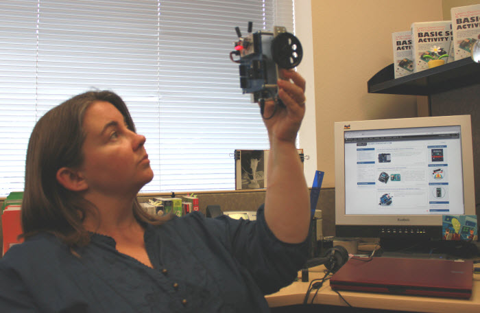
Always use this IrInterferenceSniffer to make sure that any area where you are using the BOE Shield-Bot is free of infrared interference.
You may have noticed that brighter car headlights (or a brighter flashlight) can be used to see objects that are further away when it’s dark. By making the BOE Shield-Bot’s infrared LED headlights brighter, you can also increase its detection range. A smaller resistor allows more current to flow through an LED. More current through an LED is what causes it to glow more brightly. In this activity, you will examine the effect of different resistance values with both the red and infrared LEDs.
You will need some extra parts for this activity:
(2) Resistors, 470 Ω (yellow-violet-brown)
(2) Resistors, 220 Ω (red-red-brown)
(2) Resistors, 1 kΩ (brown-black-red)
(2) Resistors, 4.7 kΩ (yellow-violet-red)
First, let’s use one of the red LEDs to see the difference that a resistor makes in how brightly an LED glows. All we need to test the LED is a sketch that sends a high signal to the LED.
// Robotics with the BOE Shield - LeftLedOn
// Turn on left LED for brightness testing

void setup()                                 // Built-in initialization block
{
  tone(4, 3000, 1000);                       // Play tone for 1 second
  delay(1000);                               // Delay to finish tone

  pinMode(8, OUTPUT);                        // Left indicator LED
  digitalWrite(8, HIGH);
}

void loop()                                  // Main loop auto-repeats
{
}
Remember to disconnect power and the programming cable before you make changes to a circuit. Remember also that the same sketch will run again when you reconnect power, so you can pick up right where you left off with each test.
We now know that less series resistance will make an LED glow more brightly. A reasonable hypothesis would be that brighter IR LEDs can make it possible to detect objects that are further away.
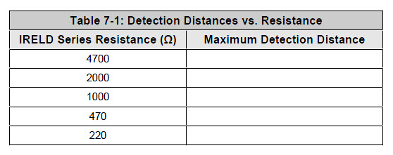
An interesting thing about these IR detectors is that their outputs are just like the whiskers. When no object is detected, the output is high; when an object is detected, the output is low. In this activity, the example sketch RoamingWithWhiskers is modified so that it works with the IR detectors; all it takes is few simple modifications. Here are the steps:
int irDetect(int irLedPin, int irReceiverPin, long frequency)
{
  tone(irLedPin, frequency, 8);
  delay(1);
  int ir = digitalRead(irReceiverPin);
  delay(1);
  return ir;
}
  byte wLeft = digitalRead(5);
  byte wRight = digitalRead(7);
…with these calls to irDetect:
  int irLeft = irDetect(9, 10, 38000);
  int irRight = irDetect(2, 3, 38000);
/*
 * Robotics with the BOE Shield - RoamingWithIr
 * Adaptation of RoamingWithWhiskers with IR object detection instead of
 * contact switches.
 */

#include <Servo.h>                           // Include servo library

Servo servoLeft;                             // Declare left and right servos
Servo servoRight;

void setup()                                 // Built-in initialization block
{
  pinMode(10, INPUT);  pinMode(9, OUTPUT);   // Left IR LED & Receiver
  pinMode(3, INPUT);  pinMode(2, OUTPUT);    // Right IR LED & Receiver

  tone(4, 3000, 1000);                       // Play tone for 1 second
  delay(1000);                               // Delay to finish tone

  servoLeft.attach(13);                      // Attach left signal to pin 13
  servoRight.attach(12);                     // Attach right signal to pin 12
}

void loop()                                  // Main loop auto-repeats
{
  int irLeft = irDetect(9, 10, 38000);       // Check for object on left
  int irRight = irDetect(2, 3, 38000);       // Check for object on right

  if((irLeft == 0) && (irRight == 0))        // If both sides detect
  {
    backward(1000);                          // Back up 1 second
    turnLeft(800);                           // Turn left about 120 degrees
  }
  else if(irLeft == 0)                       // If only left side detects
  {
    backward(1000);                          // Back up 1 second
    turnRight(400);                          // Turn right about 60 degrees
  }
  else if(irRight == 0)                      // If only right side detects
  {
    backward(1000);                          // Back up 1 second
    turnLeft(400);                           // Turn left about 60 degrees
  }
  else                                       // Otherwise, no IR detected
  {
    forward(20);                             // Forward 1/50 of a second
  }
}

int irDetect(int irLedPin, int irReceiverPin, long frequency)
{
  tone(irLedPin, frequency, 8);              // IRLED 38 kHz for at least 1 ms
  delay(1);                                  // Wait 1 ms
  int ir = digitalRead(irReceiverPin);       // IR receiver -> ir variable
  delay(1);                                  // Down time before recheck
  return ir;                                 // Return 1 no detect, 0 detect
}

void forward(int time)                       // Forward function
{
  servoLeft.writeMicroseconds(1700);         // Left wheel counterclockwise
  servoRight.writeMicroseconds(1300);        // Right wheel clockwise
  delay(time);                               // Maneuver for time ms
}

void turnLeft(int time)                      // Left turn function
{
  servoLeft.writeMicroseconds(1300);         // Left wheel clockwise
  servoRight.writeMicroseconds(1300);        // Right wheel clockwise
  delay(time);                               // Maneuver for time ms
}

void turnRight(int time)                     // Right turn function
{
  servoLeft.writeMicroseconds(1700);         // Left wheel counterclockwise
  servoRight.writeMicroseconds(1700);        // Right wheel counterclockwise
  delay(time);                               // Maneuver for time ms
}

void backward(int time)                      // Backward function
{
  servoLeft.writeMicroseconds(1300);         // Left wheel clockwise
  servoRight.writeMicroseconds(1700);        // Right wheel counterclockwise
  delay(time);                               // Maneuver for time ms
}
The style of pre-programmed maneuvers from the last activity were fine for whiskers, but are unnecessarily slow when using the IR detectors. With whiskers, the BOE Shield-Bot had to make contact and then back up to navigate around obstacles. With infrared, your BOE Shield-Bot will detect most obstacles before it runs into them, and can just find a clear path around the obstacle.
You can reduce all your maneuver durations to 20 ms, which means your sketch will check and recheck for objects almost 50 times per second. (It’s actually a little slower, more like 40 times per second, because the code execution and IR detection all takes time too.) As your BOE Shield-Bot navigates, it will execute a series of small turns to avoid an obstacle before it ever runs into it. With that approach, it never turns further than it has to, and it can neatly find its way around obstacles and successfully navigate more complex courses. After experimenting with this next sketch, you’ll likely agree that it’s a much better way for the BOE Shield-Bot to roam.
/*
 * Robotics with the BOE Shield - FastIrRoaming
 * Adaptation of RoamingWithWhiskers with IR object detection instead of
 * contact switches
 */

#include <Servo.h>                           // Include servo library

Servo servoLeft;                             // Declare left and right servos
Servo servoRight;

void setup()                                 // Built-in initialization block
{
  pinMode(10, INPUT);  pinMode(9, OUTPUT);   // Left IR LED & Receiver
  pinMode(3, INPUT);  pinMode(2, OUTPUT);    // Right IR LED & Receiver

  tone(4, 3000, 1000);                       // Play tone for 1 second
  delay(1000);                               // Delay to finish tone

  servoLeft.attach(13);                      // Attach left signal to pin 13
  servoRight.attach(12);                     // Attach right signal to pin 12
}

void loop()                                  // Main loop auto-repeats
{

  int irLeft = irDetect(9, 10, 38000);       // Check for object on left
  int irRight = irDetect(2, 3, 38000);       // Check for object on right

  if((irLeft == 0) && (irRight == 0))        // If both sides detect
  {
    maneuver(-200, -200, 20);                // Backward 20 milliseconds
  }
  else if(irLeft == 0)                       // If only left side detects
  {
    maneuver(200, -200, 20);                 // Right for 20 ms
  }
  else if(irRight == 0)                      // If only right side detects
  {
    maneuver(-200, 200, 20);                 // Left for 20 ms
  }
  else                                       // Otherwise, no IR detects
  {
    maneuver(200, 200, 20);                  // Forward 20 ms
  }
}

int irDetect(int irLedPin, int irReceiverPin, long frequency)
{
  tone(irLedPin, frequency, 8);              // IRLED 38 kHz for at least 1 ms
  delay(1);                                  // Wait 1 ms
  int ir = digitalRead(irReceiverPin);       // IR receiver -> ir variable
  delay(1);                                  // Down time before recheck
  return ir;                                 // Return 1 no detect, 0 detect
}

void maneuver(int speedLeft, int speedRight, int msTime)
{
  // speedLeft, speedRight ranges: Backward  Linear  Stop  Linear   Forward
  //                               -200      -100......0......100       200
  servoLeft.writeMicroseconds(1500 + speedLeft);   // Set left servo speed
  servoRight.writeMicroseconds(1500 - speedRight); // Set right servo speed
  if(msTime==-1)                                   // if msTime = -1
  {
    servoLeft.detach();                            // Stop servo signals
    servoRight.detach();
  }
  delay(msTime);                                   // Delay for msTime
}
This sketch uses the maneuver function from the TestManeuverFunction sketch. The maneuver function expects three parameters: speedLeft, speedRight, and msTime. Recall that both speed parameters use 200 for full speed forward, ‑200 for full speed backward, and values between -100 and +100 for linear speed control. Also, remember msTime values are 20, so each maneuver executes for 20 ms before returning to the loop function.
void loop()                                  // Main loop auto-repeats
{
  int irLeft = irDetect(9, 10, 38000);       // Check for object on left
  int irRight = irDetect(2, 3, 38000);       // Check for object on right

  if((irLeft == 0) && (irRight == 0))        // If both sides detect
  {
    maneuver(-200, -200, 20);                // Backward 20 milliseconds
  }
  else if(irLeft == 0)                       // If only left side detects
  {
    maneuver(200, -200, 20);                 // Right for 20 ms
  }
    else if(irRight == 0)                    // If only right side detects
  {
    maneuver(-200, 200, 20);                 // Left for 20 ms
  }
  else                                       // Otherwise, no IR detects
  {
    maneuver(200, 200, 20);                  // Backward 20 ms
  }
}
Up until now, your robot has mainly been programmed to take evasive maneuvers when an object is detected. There are also applications where the BOE Shield-Bot must take evasive action when an object is not detected. For example, if the BOE Shield-Bot is roaming on a table, its IR detectors might be looking down at the table surface. The sketch should make it continue forward so long as both IR detectors can “see” the surface of the table.
]

(1) Roll of black vinyl electrical tape, ¾″ (19 mm) wide, or black tempera paint and brush.
(1) Sheet of white poster board, 22 x 28 in (56 x 71 cm).
A sheet of white poster board with a border made of electrical tape or black tempera paint makes for a handy way to simulate the drop-off presented by a table edge, with much less risk to your BOE Shield-Bot.

If you are using older IR LEDs, the BOE Shield-Bot might actually be having problems with being too nearsighted. Here are some remedies that will increase the BOE Shield-Bot’s sensitivity to objects and make it more far sighted:
Make sure to be the spotter for your BOE Shield-Bot. It’s best to keep your hand poised so that you are ready to pick it up from above. Be ready as your BOE Shield-Bot roams the tabletop:
For the most part, programming your BOE Shield-Bot to navigate around a tabletop without going over the edge is a matter of adjusting the if…else if…else statements from FastIrRoaming. First of all, instead of backing up, it will need to go forward 20 ms at a time when it sees objects with both detectors. It will also need to turn toward objects instead of away from them, and it will need to turn for more than 20 ms when it sees the drop-off. 375 ms turns seem to work well, but it will be up to you to adjust that value for best performance.
/*
 * Robotics with the BOE Shield - AvoidTableEdge
 * Adaptation of FastIrRoaming for table edge avoidance
 */

#include <Servo.h>                           // Include servo library

Servo servoLeft;                             // Declare left and right servos
Servo servoRight;

void setup()                                 // Built-in initialization block
{
  pinMode(10, INPUT);  pinMode(9, OUTPUT);   // Left IR LED & Receiver
  pinMode(3, INPUT);  pinMode(2, OUTPUT);    // Right IR LED & Receiver

  tone(4, 3000, 1000);                       // Play tone for 1 second
  delay(1000);                               // Delay to finish tone

  servoLeft.attach(13);                      // Attach left signal to pin 13
  servoRight.attach(12);                     // Attach right signal to pin 12
}

void loop()                                  // Main loop auto-repeats
{

  int irLeft = irDetect(9, 10, 38000);       // Check for object on left
  int irRight = irDetect(2, 3, 38000);       // Check for object on right

  if((irLeft == 0) && (irRight == 0))        // Both sides see table surface
  {
    maneuver(200, 200, 20);                  // Forward 20 milliseconds
  }
  else if(irLeft == 0)                       // Left OK, drop-off on right
  {
    maneuver(-200, 200, 375);                // Left for 375 ms
  }
  else if(irRight == 0)                      // Right OK, drop-off on left
  {
    maneuver(200, -200, 375);                // Right for 375 ms
  }
  else                                       // Drop-off straight ahead
  {
    maneuver(-200, -200, 250);               // Backward 250 ms before retry
  }
}

int irDetect(int irLedPin, int irReceiverPin, long frequency)
{
  tone(irLedPin, frequency, 8);              // IRLED 38 kHz for at least 1 ms
  delay(1);                                  // Wait 1 ms
  int ir = digitalRead(irReceiverPin);       // IR receiver -> ir variable
  delay(1);                                  // Down time before recheck
  return ir;                                 // Return 1 no detect, 0 detect
}

void maneuver(int speedLeft, int speedRight, int msTime)
{
  // speedLeft, speedRight ranges: Backward  Linear  Stop  Linear   Forward
  //                               -200      -100......0......100       200
  servoLeft.writeMicroseconds(1500 + speedLeft);   // Set left servo speed
  servoRight.writeMicroseconds(1500 - speedRight); // Set right servo speed
  if(msTime==-1)                                   // if msTime = -1
  {
    servoLeft.detach();                            // Stop servo signals
    servoRight.detach();
  }
  delay(msTime);                                   // Delay for msTime
}
Since AvoidTableEdge is just FastIrRoaming with a modified if…else if…else statement in it’s loop function, let’s look at the two statements side by side.
// From FastIrRoaming

  if((irLeft == 0) && (irRight == 0))
  {
    maneuver(-200, -200, 20);
  }
  else if(irLeft == 0)
  {
    maneuver(200, -200, 20);
  }
  else if(irRight == 0)
  {
    maneuver(-200, 200, 20);
  }
  else
  {
    maneuver(200, 200, 20);
  }
|
//From AvoidTableEdge

  if((irLeft == 0) && (irRight == 0))
  {
    maneuver(200, 200, 20);
  }
  else if(irLeft == 0)
  {
    maneuver(-200, 200, 375);
  }
  else if(irRight == 0)
  {
    maneuver(200, -200, 375);
  }
  else
  {
    maneuver(-200, -200, 250);
  }
}
|
In response to if((irLeft == 0) && (irRight == 0)), FastIrRoaming backs up with maneuver(-200, -200, 20) because both IR detectors see an obstacle. In contrast, AvoidTableEdge goes forward with maneuver(200, 200, 20) because both IR detectors see the table, which means it’s safe to move forward for another 20 ms.
In response to else if(irLeft == 0), FastIrRoaming turns right for 20 ms, taking a step toward avoiding an obstacle on the left with maneuver(200, -200, 20). AvoidTableEdge instead turns away from a drop-off that must be on it’s right. That’s because the first if statement where both IR detectors could see the table was not true. If it was, the if…else if…else statement would not have made it to this else if condition. It means the left IR detector does see the table, but the right one does not. So the code makes the BOE Shield turn left for 0.375 seconds with maneuver(-200, 200, 375). This should make it avoid a drop-off that must have been detected on the right.
In response to else if (irRight == 0), FastIrRoaming turns left for 20 ms, taking an incremental step toward avoiding an obstacle on the right. At this point in the if…else if…else statement, we know that the right IR detector does see an object, but the left one does not. Again, that’s because, it would have handled the condition where both IR detectors see the table with the first if statement. So, the left IR detector does not see the object and turns right for 0.375 seconds with maneuver(200, -200, 375).
The 375 ms turns to avoid the table edge can be adjusted for different applications. For example, if the BOE Shield-Bot is supposed to hug the edge of the table, smaller turns might be useful. In a contest where the BOE Shield-Bot is supposed to push objects out of an area, a larger turn (but not too large) would be better so that it zigzags back and forth across the table.
You can modify the code to make shallower turns by using a smaller msTime parameter value in the maneuver function calls. For example, if you change the 375 in maneuver(-200, 200, 375) to 300, it will make shallower left turns. If you change it to 450, it will make sharper left turns.
This chapter focused on using a pair of infrared LED emitters and receivers to broadcast and detect reflections of 38.5 kHz modulated infrared light. Using this sensor system for robot navigation used these concepts and skills:
  int irLeft = 1;                         // Declare IR variables and
  int irRight = 1;                        // initialize both to 1

  while((irLeft == 1) && (irRight == 1))  // Wait for detection
  {
    irLeft = irDetect(9, 10, 38000);      // Check for object on left
    irRight = irDetect(2, 3, 38000);      // Check for object on right
  }
Now, to chase after an object, the if…else if…else statement needs to be updated so that it goes forward when it sees an object with both sensors. It should also turn toward an object instead of away from it. Here is a modified loop function.
void loop()                              // Main loop auto-repeats
{

  int irLeft = irDetect(9, 10, 38000);   // Check for object on left
  int irRight = irDetect(2, 3, 38000);   // Check for object on right

  if((irLeft == 0) && (irRight == 0))    // If both sides detect
  {
    maneuver(200, 200, 20);              // Forward 20 ms, chase object
  }
  else if(irLeft == 0)                   // If only left side detects
  {
    maneuver(-200, 200, 20);             // Left toward object 20 ms
  }
    else if(irRight == 0)                // If only right side detects
  {
    maneuver(200, -200, 20);             // Right toward object 20 ms
  }
  else                                   // Otherwise, no IR detects
  {
    maneuver(200, 200, 20);              // Forward 20 ms
  }
}
The example above goes forward for 20 ms if it does not see the object. Optionally, it could spin in place until it sees an object and then chase after it again. For this, you could place the code that spins and waits for a detection in a function. Then, your code could call that function from the end of the setup function to wait until it sees something, and also from the else statement in the loop function for when it can’t see the object any more.
void setup()                                 // Built-in initialization block
{
  pinMode(10, INPUT);  pinMode(9, OUTPUT);   // Left IR LED & Receiver
  pinMode(3, INPUT);  pinMode(2, OUTPUT);    // Right IR LED & Receiver
  pinMode(8, OUTPUT); pinMode(7, OUTPUT);    // LED indicators -> output

  tone(4, 3000, 1000);                       // Play tone for 1 second
  delay(1000);                               // Delay to finish tone

  servoLeft.attach(13);                      // Attach left signal to pin 13
  servoRight.attach(12);                     // Attach right signal to pin 12
}

void loop()                                  // Main loop auto-repeats
{
  // Sniff

  int irLeft = digitalRead(10);              // Check for IR on left
  int irRight = digitalRead(3);              // Check for IR on right

  if((irLeft == 0) || (irRight == 0))
  {
    for(int i = 0; i < 5; i++)               // Repeat 5 times
    {
      digitalWrite(7, HIGH);                 // Turn indicator LEDs on
      digitalWrite(8, HIGH);
      tone(4, 4000, 10);                     // Sound alarm tone
      delay(20);                             // 10 ms tone, 10 between tones
      digitalWrite(7, LOW);                  // Turn indicator LEDs off
      digitalWrite(8, LOW);
    }
  }

  // Roam

  irLeft = irDetect(9, 10, 38000);       // Check for object on left
  irRight = irDetect(2, 3, 38000);       // Check for object on right

  if((irLeft == 0) && (irRight == 0))        // If both sides detect
  {
    maneuver(-200, -200, 20);                // Backward 20 milliseconds
  }
  else if(irLeft == 0)                       // If only left side detects
  {
    maneuver(200, -200, 20);                 // Right for 20 ms
  }
    else if(irRight == 0)                    // If only right side detects
  {
    maneuver(-200, 200, 20);                 // Left for 20 ms
  }
  else                                       // Otherwise, no IR detects
  {
    maneuver(200, 200, 20);                  // Forward 20 ms
  }
}
In Chapter 7, we used the infrared LEDs and receivers to detect whether an object is in the BOE Shield-Bot’s way without actually touching it. Wouldn’t it be nice to also get some distance information from the IR sensors? There is a way to accomplish some rough, close-range detection with the very same IR circuit from the previous chapter. It’s just enough information to allow the BOE Shield-Bot to follow a moving object without colliding into it.
]
This chapter uses the same IR LED/receiver circuits from the previous chapter.
You will also need:
(1) ruler
(1) sheet of paper
Here’s a graph from one specific brand of IR detector’s datasheet (Panasonic PNA4602M; a different brand may have been used in your kit).

The graph shows that the IR detector is most sensitive at 38.5 kHz—its peak sensitivity —at the top of the curve. Notice how quickly the curve drops on both sides of the peak. This IR detector is much less sensitive to IR signals that flash on/off at frequencies other than 38 kHz. It’s only half as sensitive to an IR LED flashing at 40 kHz as it would be to 38 kHz signals. For an IR LED flashing at 42 kHz, the detector is only 20% as sensitive. The further from 38 kHz an IR LED’s signal rate is, the closer the IR receiver has to be to an object to see that IR signal’s reflection.
The most sensitive frequency (38 kHz) will detect the objects that are the farthest away, while less-sensitive frequencies can only detect closer objects. This makes rough distance detection rather simple: pick some frequencies, then test them from most sensitive to least sensitive. Try the most sensitive frequency first. If an object is detected, check and see if the next-most sensitive frequency detects it. Depending on which frequency makes the reflected infrared no longer visible to the IR detector, your sketch can infer a rough distance.
Frequency Sweep is the technique of testing a circuit’s output using a variety of input frequencies.
The next diagram shows an example of how the BOE Shield-Bot can test for distance using frequency. In this example, an object is in Zone 3. That means that the object can be detected when 38000 and 39000 Hz is transmitted, but it cannot be detected with 40000, 41000, or 42000 Hz. If you were to move the object into Zone 2, then the object would be detected when 38000, 39000, and 40000 Hz are transmitted, but not with 41000 or 42000 Hz.

The irDistance function from the next sketch performs distance measurement using the technique shown above. Code in the main loop calls irDistance and passes it values for a pair of IR LED and receiver pins. For example, the loop function uses int irLeft = irDistance(9, 10) to check distance to an object in the left side of the BOE Shield-Bot’s detection zone “field of vision.”
// IR distance measurement function

int irDistance(int irLedPin, int irReceivePin)
{
  int distance = 0;
  for(long f = 38000; f <= 42000; f += 1000) {
    distance += irDetect(irLedPin, irReceivePin, f);
  }
  return distance;
}
The irDetect function returns a 1 if it doesn’t see an object, or a zero if it does. The expression distance += irDetect(irLedPin, irReceivePin, f) counts the number of times the object is not detected. After the for loop is done, that distance variable stores the number of times the IR detector did not see an object. The more times it doesn’t see an object, the further away it must be. So, the distance value the function returns represents the zone number in the drawing above.
It’s important to test that the detection distances are roughly the same for both IR LED/receiver pairs. They don’t have to be identical, but if they are too far apart, the BOE Shield-Bot might have difficulty following an object in front of it because it will keep trying to turn to one side. More subsystem testing!
A common cause of mismatched distance measurement is mismatched resistors used with the IR LEDs. For example, if one side’s IR LED has a 1 kΩ resistor and the other has a 2 kΩ resistor, one side will need objects to be much closer to see them. Another possibility, though rare, is that one IR detector is far more sensitive than the other. In that case, a larger resistor can be used in series with the IR LED on that side to make its IR headlight dimmer and correct the mismatched measurements.
This screencapture shows some detection zone measurements from DisplayBothDistances in the Serial Monitor. Though there’s fluctuation in the values, commonly called noise, what matters is that the numbers match, or are off by only 1, in each pair of measurements.
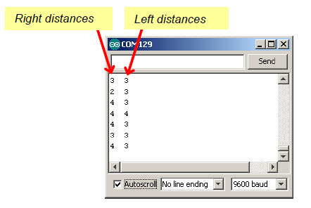
/*
 * Robotics with the BOE Shield - DisplayBothDistances
 * Display left and right IR states in Serial Monitor.
 * Distance range is from 0 to 5.  Only a small range of several centimeters
 * in front of each detector is measureable.  Most of it will be 0 (too
 * close) or 5 (too far).
 */

void setup()                                 // Built-in initialization block
{
  tone(4, 3000, 1000);                       // Play tone for 1 second
  delay(1000);                               // Delay to finish tone

  pinMode(10, INPUT);  pinMode(9, OUTPUT);   // Left IR LED & Receiver
  pinMode(3, INPUT);  pinMode(2, OUTPUT);    // Right IR LED & Receiver

  Serial.begin(9600);                        // Set data rate to 9600 bps
}

void loop()                                  // Main loop auto-repeats
{
  int irLeft = irDistance(9, 10);            // Measure left distance
  int irRight = irDistance(2, 3);            // Measure right distance

  Serial.print(irLeft);                      // Display left distance
  Serial.print("  ");                        // Display spaces
  Serial.println(irRight);                   // Display right distance

  delay(100);                                // 0.1 second delay
}

// IR distance measurement function

int irDistance(int irLedPin, int irReceivePin)
{
  int distance = 0;
  for(long f = 38000; f <= 42000; f += 1000) {
    distance += irDetect(irLedPin, irReceivePin, f);
  }
  return distance;
}

// IR Detection function

int irDetect(int irLedPin, int irReceiverPin, long frequency)
{
  tone(irLedPin, frequency, 8);              // IRLED 38 kHz for at least 1 ms
  delay(1);                                  // Wait 1 ms
  int ir = digitalRead(irReceiverPin);       // IR receiver -> ir variable
  delay(1);                                  // Down time before recheck
  return ir;                                 // Return 1 no detect, 0 detect
}
For a BOE Shield-Bot to follow a leader-object, it has to know the rough distance to the leader. If the leader is too far away, the sketch has to be able to detect that and move the BOE Shield-Bot forward. Likewise, if the leader is too close, the sketch has to detect that and move the BOE Shield-Bot backward. The purpose of the sketch is to make the BOE Shield-Bot maintain a certain distance between itself and the leader-object.
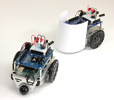
When a machine is designed to automatically maintain a measured value, it generally involves a control system. The value that the system is trying to maintain is called the set point. Electronic control systems often use a processor to take sensor measurements and respond by triggering mechanical actuators to return the machine to the set point.
Our machine is the BOE Shield-Bot. The measured value we want it to maintain is the distance to the leader-object, with a set point of 2 (for zone 2). The machine’s processor is the Arduino. The IR LED/receiver pairs are the sensors that take distance value measurements to the leader-object. If the measured distance is different from the set-point distance, the servos are the mechanical actuators that rotate to move the BOE Shield-Bot forward or backward as needed.
Closed loop control—repeatedly measuring a value and adjusting output in proportion to error for maintaining a set point—works very well for the BOE Shield-Bot shadow vehicle. In fact, the majority of the control loop shown in the diagram below reduces to just one line of code in a sketch. This block diagram describes the proportional control process that the BOE Shield-Bot will use to control the wheel speed based on detection distance measured with the IR LED/receiver pairs.
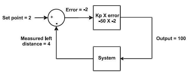
This block diagram could apply to either the left IR distance sensor and servo output or the right. In fact, your code will maintain two identical control loops, one for each side of the BOE Shield-Bot. Let’s walk through this example.
In the upper left, the set point = 2; we want the BOE Shield-Bot to maintain a zone-2 distance between itself and its leader-object. Below that, the measured distance is zone 4, so the leader-object is too far away. The arrows towards the symbols in the circle (called a summing junction) indicate that you add (+) the set point and subtract (-) the measured distance together to get the error, in this case 2 – 4 = -2.
Next, the error value feeds into the top square—an operator block. This block shows that the error gets multiplied by -50, a proportionality constant (Kp). In this example, the operator block gives us -2 × -50 = 100, so 100 is the output. In a sketch, this output value gets passed to the maneuver function. It turns the servo full speed forward to move the BOE Shield bot closer to the leader-object.
The next block diagram shows another example. This time, the measured distance is 1, meaning the leader-object is too close. So, the error is 1, and 1×–50 = -50. Passing -50 to the maneuver function turns the servo half-speed in reverse, backing the BOE Shield-Bot away from the leader-object.

The next time through the loop, the measured distance might change, but that’s okay. Regardless of the measured distance, this control loop will calculate a value that will cause the servo to move to correct any error. The correction is always proportional to the error. The two calculations involved:
set point – measured distance = error; error x Kp = output for maneuver
…can be easily combined and re-ordered into one expression for your sketch:
Output for maneuver = (Distance set point – Measured distance) x Kp
If you want to take a look at the sketch in detail, see How FollowingShieldBot Works.
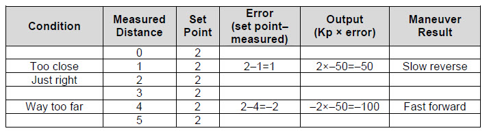
The FollowingShieldBot sketch repeats the proportional control loops just discussed at a rate of about 25 times per second. So, all the proportional control calculations and servo speed updates happen 25 times each second. The result is a BOE Shield-Bot that will follow your hand, a book, or another robot.
/*
 * Robotics with the BOE Shield - FollowingShieldBot
 * Use proportional control to maintain a fixed distance between
 * BOE Shield-Bot and object in front of it.
 */

#include <Servo.h>                           // Include servo library

Servo servoLeft;                             // Declare left and right servos
Servo servoRight;

const int setpoint = 2;                      // Target distances
const int kpl = -50;                         // Proportional control constants
const int kpr = -50;

void setup()                                 // Built-in initialization block
{
  pinMode(10, INPUT);  pinMode(9, OUTPUT);   // Left IR LED & Receiver
  pinMode(3, INPUT);  pinMode(2, OUTPUT);    // Right IR LED & Receiver

  tone(4, 3000, 1000);                       // Play tone for 1 second
  delay(1000);                               // Delay to finish tone

  servoLeft.attach(13);                      // Attach left signal to pin 13
  servoRight.attach(12);                     // Attach right signal to pin 12
}

void loop()                                  // Main loop auto-repeats
{
  int irLeft = irDistance(9, 10);            // Measure left distance
  int irRight = irDistance(2, 3);            // Measure right distance

  // Left and right proportional control calculations
  int driveLeft = (setpoint - irLeft) * kpl;
  int driveRight = (setpoint - irRight) * kpr;

  maneuver(driveLeft, driveRight, 20);       // Drive levels set speeds
}

// IR distance measurement function

int irDistance(int irLedPin, int irReceivePin)
{
  int distance = 0;
  for(long f = 38000; f <= 42000; f += 1000) {
    distance += irDetect(irLedPin, irReceivePin, f);
  }
  return distance;
}

// IR Detection function

int irDetect(int irLedPin, int irReceiverPin, long frequency)
{
  tone(irLedPin, frequency, 8);              // IRLED 38 kHz for at least 1 ms
  delay(1);                                  // Wait 1 ms
  int ir = digitalRead(irReceiverPin);       // IR receiver -> ir variable
  delay(1);                                  // Down time before recheck
  return ir;                                 // Return 1 no detect, 0 detect
}

void maneuver(int speedLeft, int speedRight, int msTime)
{
  // speedLeft, speedRight ranges: Backward  Linear  Stop  Linear   Forward
  //                               -200      -100......0......100       200
  servoLeft.writeMicroseconds(1500 + speedLeft);   // Set left servo speed
  servoRight.writeMicroseconds(1500 - speedRight); // Set right servo speed
  if(msTime==-1)                                   // if msTime = -1
  {
    servoLeft.detach();                            // Stop servo signals
    servoRight.detach();
  }
  delay(msTime);                                   // Delay for msTime
}
FollowingShieldBot declares three global constants: setpoint, kpl, and kpr. Everywhere you see setpoint, it’s actually the number 2 (a constant). Likewise, everywhere you see kpl, it’s actually the number -50. Likewise with kpr.
const int setpoint = 2;                      // Target distances
const int kpl = -50;                         // Proportional control constants
const int kpr = -50;
The convenient thing about declaring constants for these values is that you can change them in one place, at the beginning of the sketch. The changes you make at the beginning of the sketch will be reflected everywhere these constants are used. For example, by changing the declaration for kpl from -50 to -45, every instance of kpl in the entire sketch changes from ‑50 to -45. This is exceedingly useful for experimenting with and tuning the right and left proportional control loops.
The first thing the loop function does is call the irDistance function for current distance measurements and copies the results to the irLeft and irRight variables.
void loop()                                  // Main loop auto-repeats
{
  int irLeft = irDistance(9, 10);            // Measure left distance
  int irRight = irDistance(2, 3);            // Measure right distance
Remember the simple control loop calculation?
Output for maneuver = (Distance set point – Measured distance) x Kp
The next two lines of code perform those calculations for the right and left control loops, and store the output-for-maneuver results to variables named driveLeft and driveRight.
  // Left and right proportional control calculations
  int driveLeft = (setpoint - irLeft) * kpl;
  int driveRight = (setpoint - irRight) * kpr;
Now, driveLeft and driveRight are ready to be passed to the maneuver function to set the servo speeds.
  maneuver(driveLeft, driveRight, 20);       // Drive levels set speeds
}
Since each call to maneuver lasts for 20 ms, it delays the loop function from repeating for 20 ms. The IR distance detection takes another 20 ms, so the loop repetition time is about 40 ms. In terms of sampling rate, that translates to 25 samples per second.
Sampling Rate vs. Sample Interval
The sample interval is the time between one sample and the next. The sampling rate is the frequency at which the samples are taken. If you know one term, you can always figure out the other:
sampling rate = 1 ÷ sample interval
Here’s a leader BOE Shield-Bot followed by a shadow BOE Shield-Bot. The lead robot is running a modified version of FastIrRoaming (with maneuver speeds reduced to +/- 40). The shadow BOE Shield-Bot is running FollowingShieldBot. One lead robot can string along a chain of 6 or 7 shadow robots. Just add the paper panel to the rest of the shadow BOE Shield-Bots in the chain.

/*
 * Robotics with the BOE Shield - SlowerIrRoamingForLeaderBot
 * Adaptation of RoamingWithWhiskers with IR object detection instead of
 * contact switches
 */

#include <Servo.h>                           // Include servo library

Servo servoLeft;                             // Declare left and right servos
Servo servoRight;

void setup()                                 // Built-in initialization block
{
  pinMode(10, INPUT);
  pinMode(9, OUTPUT);   // Left IR LED & Receiver
  pinMode(3, INPUT);
  pinMode(2, OUTPUT);    // Right IR LED & Receiver

  tone(4, 3000, 1000);                       // Play tone for 1 second
  delay(1000);                               // Delay to finish tone

  servoLeft.attach(13);                      // Attach left signal to pin 13
  servoRight.attach(12);                     // Attach right signal to pin 12
}

void loop()                                  // Main loop auto-repeats
{

  int irLeft = irDetect(9, 10, 38000);       // Check for object on left
  int irRight = irDetect(2, 3, 38000);       // Check for object on right

  if((irLeft == 0) && (irRight == 0))        // If both sides detect
  {
    maneuver(-40, -40, 20);                // Backward 20 milliseconds
  }
  else if(irLeft == 0)                       // If only left side detects
  {
    maneuver(40, -40, 20);                 // Right for 20 ms
  }
  else if(irRight == 0)                      // If only right side detects
  {
    maneuver(-40, 40, 20);                 // Left for 20 ms
  }
  else                                       // Otherwise, no IR detects
  {
    maneuver(40, 40, 20);                  // Forward 20 ms
  }
}

int irDetect(int irLedPin, int irReceiverPin, long frequency)
{
  tone(irLedPin, frequency, 8);              // IRLED 38 kHz for at least 1 ms
  delay(1);                                  // Wait 1 ms
  int ir = digitalRead(irReceiverPin);       // IR receiver -> ir variable
  delay(1);                                  // Down time before recheck
  return ir;                                 // Return 1 no detect, 0 detect
}

void maneuver(int speedLeft, int speedRight, int msTime)
{
  // speedLeft, speedRight ranges: Backward  Linear  Stop  Linear   Forward
  //                               -200      -100......0......100       200
  servoLeft.writeMicroseconds(1500 + speedLeft);   // Set left servo speed
  servoRight.writeMicroseconds(1500 - speedRight); // Set right servo speed
  if(msTime==-1)                                   // if msTime = -1
  {
    servoLeft.detach();                            // Stop servo signals
    servoRight.detach();
  }
  delay(msTime);                                   // Delay for msTime
}
You can adjust the setpoint and proportionality constants to change the shadow BOE Shield-Bot’s behavior. Use your hand or a piece of paper to lead the shadow BOE Shield-Bot while doing these exercises:
You might notice some odd behaviors. For example, if the set point is 0, it won’t back up. Want to figure out why?
Congratulations! You’ve made it to the end of the book. Now that you’ve mastered the basics, you’re ready to start exploring and adding capabilities with your BOE Shield-Bot! Here are some ideas:
Or, if you’re interested in trying specific sensors or adapting projects from other platforms, take a look at some of the options below.
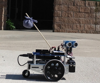
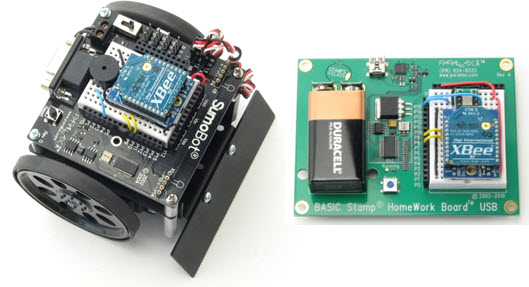
This chapter used the infrared IR LED/receiver pairs for simple distance detection, to make a BOE Shield-Bot shadow vehicle. Now-familiar skills combined with some new concepts got the job done:
  for(long f = 38000; f <= 42000; f += 1000) {
    distance += irDetect(irLedPin, irReceivePin, f);
  }
const int setpoint = 2;    // Target distances
const int kpl = -45;       // Proportional control constants
const int kpr = -55;
void loop()                          // Main loop auto-repeats
{
  int irLeft = irDistance(9, 10);    // Measure left distance
  int irRight = irDistance(2, 3);    // Measure right distance

  // Left and right proportional control calculations
  int driveLeft = (setpoint - irLeft) * kpl;
  int driveRight = (setpoint - irRight) * kpr;

  int drive = (driveLeft + driveRight)/2; // Average drive levels

  maneuver(drive, drive, 20);        // Apply same drive to both

  delay(10);                         // 0.1 second delay
}