In these activities, you will take basic electrical measurements: voltage, resistance, and current. Along the way, you will learn some important rules about voltage, current and resistance behaviors in certain circuits and under certain conditions.
Being able to measure what’s happening in a circuit and understand what it means is a key ingredient in the success of many inventions. Engineers use measurements to troubleshoot their inventions and prototypes. Technicians use it to maintain and repair everything from cell phones, to supermarket doors, to main power grid components.
You will need:
Complete these tutorials first:
You will be able to:
A voltmeter is a device that measures voltage, the electrical pressure in a circuit. In this activity, you will learn how to measure the voltage across an element in a circuit using a micro:bit-based voltmeter. Knowing how to take voltage measurements is essential when working on electrical equipment. Examples include:
Let’s re-use the setup from First Breadboard Circuit — Build the LED Circuit, shown again below. In addition to the basic setup and previous LED circuit, you will need an additional resistor.
(1) LED, green
(1) Wire, black
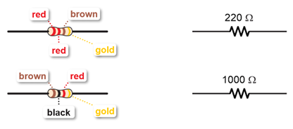
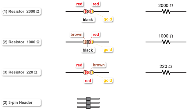
(1) Resistor, 220 ohm (red-red-brown)
(1) Resistor, 1000 ohm (brown-black-red)
measure_volts_with_cyberscope.hex
In these tests, you will measure voltages across the LED circuit’s components and compare them to the voltage across the +/- supply rails.
If you guessed from your measurements that adding up the voltages across each part in the circuit has to add up to the supply voltage, you guessed correctly.
Think about the micro:bit module’s 3.3 V supply as a (positive) increase in voltage and the parts in the LED circuit as a (negative) decrease in voltage.
Add those positive and negative voltages, and the result should be zero, in theory. In practice, your measurements should add up to something close to zero.
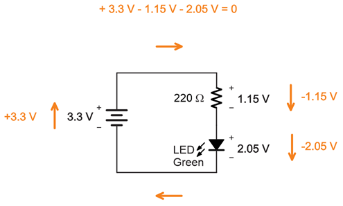
This is an application of Kirchhoff’s voltage law (abbreviated KVL), which states: “The directed sum of the potential differences (voltages) around any closed loop is zero.” When parts in a circuit are connected end-to-end like the resistor to the LED, they are connected in series.
Learn more: https://en.wikipedia.org/wiki/Kirchhoff%27s_circuit_laws.
You can change the resistor, and the sum of voltages measured across the LED and resistor should still add up to the supply voltage.
Did they still add up to 3.3 V?
Red LEDs use slightly less voltage.
Did you notice a difference in the voltages? Did they still add up to 3.3 V?
An ohmmeter is a device that measures resistance. The basic unit of resistance is the ohm, and it’s abbreviated with the uppercase Greek letter omega (Ω).
This activity will guide you through:
A test circuit cannot have power applied to while measuring resistance. This second, important rule normally applies when using a repair manual, which might direct you to measure the resistance in a much larger circuit that’s part of some device. The device’s power would have to be turned off for an ohmmeter to take a valid measurement.
In this activity you will have an ohmmeter circuit and an LED circuit. You will use the ohmmeter circuit to measure different resistors used in the LED circuit.
Let’s once again re-use the setup from First Breadboard Circuit — Build the LED Circuit.
The LED circuit may still be on your board. If not, re-build it now.
You will also need the following additional parts, along with some jumper wires:
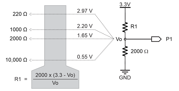
This ohmmeter circuit can measure resistances in the 100 to 10,000 Ω range.
Individual resistors need to be removed from the circuit to be measured by an ohmmeter. Keep this in mind as you follow the instructions.
TIP: When measuring individual resistors, you can also simply grab the ends of the resistors with the alligator clips.
In the diagram, R1 is the resistance of the part you are measuring. Vo is the voltage that results between R1 and the 2000 Ω resistor. The multimeter module measures the voltage between the two resistors with P1. Then, it uses the R1 = … equation near the bottom of the diagram to calculate the value of R1. For example, if P1 measures 2.97 V, the result of the equation will be 220 Ω. If P1 measures 2.2 V, the result of the equation will be 1000 Ω.
When two resistors are connected end-to-end, they are connected in series.
When voltages like 3.3 V and GND are applied to the ends of two resistors in series, it is called a voltage divider. The name came from the fact that the voltage at Vo is “divided” between the two resistors. In the Voltage Dividers lesson, you will experiment more with this and optionally derive the equation for calculating R1.
Modern multimeters expand the circuit and script to automatically measure anything from a fraction of an ohm to millions of ohms.
Let’s measure a different resistor. Keep in mind that accuracy is best in the 100 Ω to 10,000 Ω range. Outside that range, measurement errors increase, and you’d need a different resistor and some script adjustments.
Imagine you are inventing something, and your design needs a 1220 Ω resistor, or maybe a 500 Ω resistor, but your kit doesn’t have either of those! Not to worry, you can combine resistors in various ways to get resistance values that are not in your kit.
Resistors can be connected end-to-end (in series) or side-by-side (in parallel). Both series and parallel resistances can be boiled down to individual equivalent resistance values. This section will show you how.
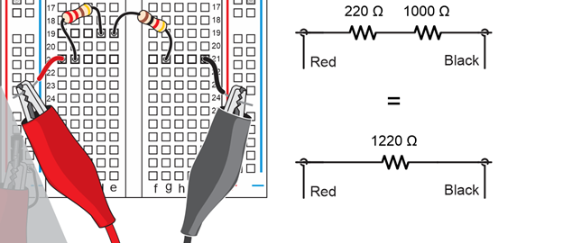
When resistors are connected end-to-end, they are connected in series. The total resistance is simply the sum of the resistors. Just add them up, and that’s the resistance.
For 2 resistors, that would be R = R1 + R2.
Example: Calculate the resistance of a 220 Ω resistor in series with a 1000 Ω resistor.
Solution: R = 220 Ω + 1000 Ω = 1220 Ω.
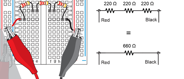
If we have some number N of resistors, the total resistance would be R = R1 + R2 + … + RN.
Example: Calculate the resistance of three 220 Ω resistors in series.
Solution: R = R1 + R2 + … + RN = 220 Ω + 220 Ω + 220 Ω = 660 Ω
In this solution, since all the resistor values are the same, you could just multiply 220 x 3.
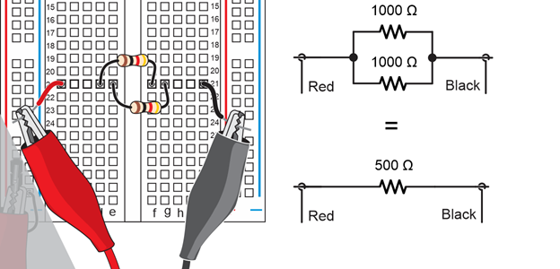
Resistors can also be connected in parallel which is side-by-side, with only two connection points where all the resistor leads are connected. (Remember, you can use a row-of-five sockets in the breadboard’s terminal strip to connect resistor leads together.)
In the special case of two resistors in parallel, the equation is R1 * R2 / (R1 + R2). For more than two, the equation is 1/(1/R1 + 1/R2 + … + 1/RN).
Example: Calculate the resistance of two 1000 Ω resistors in parallel.
Solution: R = R1 x R2 / (R1 + R2) = (1000 x 1000) / (1000 + 1000) = 1,000,000 / 2000 = 500 Ω
Example: Calculate the resistance of three 1000 Ω resistors in parallel.
Solution R = 1 / (1/R1 + 1/R2 + …+ 1/RN) = 1 / (1/1000 + 1/1000 + 1/1000) = 1 / (3/1000) = 1000/3 ≈ 333 Ω.

To figure out the equivalent resistance of a circuit with both series and parallel elements, calculate the equivalent resistance of a subcircuit that is either parallel or series first.
For example, if one resistor is in series with a pair of parallel resistors, solve for those parallel resistors first. After that, all that’s left is two resistors in series.

Another example, let’s say that one resistor is parallel to a pair of resistors in series. In that case, solve for the series resistors first. Then, all that’s left are two parallel resistors.

Series
Parallel
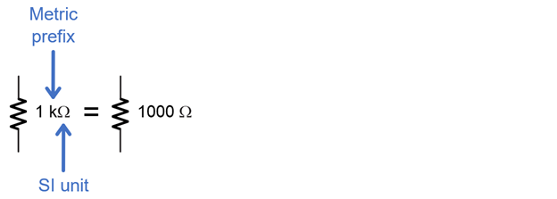
Like the rest of science and engineering, electronics relies heavily on the International System of Units, which is abbreviated SI. The abbreviation SI comes from the French name Système International, and it’s basically the modern version of the metric system. Electronics also have measurements and quantities with some very large and small values. So, instead of a schematic with values like 1000 Ω or 1 x 10³ Ω, you are likely to see 1 kΩ. In this example, k is the metric prefix for one-thousand, and the Greek letter omega Ω is symbol for ohm, the SI unit of resistance.
In this activity, you will:
The International System of Units is the modern metric system. It is abbreviated SI, from the original French “Le Système International d’Unités.”
Here’s an example of one of the most commonplace SI units -length in meters:
How is this used? One example would be if you are taking notes while measuring distances, it’s a lot easier to write L = 50 m than it is to write “the length is fifty meters”.
Here is a table of some of the common time and electric quantities and units you will use in these lessons.
| Quantity | Unit | Description | ||
|---|---|---|---|---|
| Name | Symbol | Name | Symbol | (non-technical version) |
| Time | t | second | s | This is seconds, the familar time measurement |
| Frequency | f | hertz | Hz | Repetitions per second |
| Current | I | amps or amperes | A | Flow of electrons |
| Voltage | e or V | volts | V | Electical pressure that makes current flow through circuits |
| Resistance | R | ohm | Ω | Resistance to electrtic current, which reduces the rate current flows through a circuit at a given voltage |
| Capacitance | C | farad | F | The amount of charge a device called a capacitor can store when boltage is applied to it |
Metric Prefixes are Multipliers
SI also simplifies numbers that are large and small with metric prefixes. These prefixes are multipliers for scaling the unit to which they are attached. Here are two examples:
scale for 1,000
scale for 0.001
Metric prefixes make it so that you can write 20 km instead of 20,000 m, and 3 mm instead of 0.003 m.
In these examples:
Here is a table with the common metric prefixes these lessons will use.
| Quantity | Prefix | Decimal | ||
|---|---|---|---|---|
| English Name | Name | Symbol | Value | Scientific Notation |
| Billion | giga | G | 1,000,000,000 | x 109 |
| Million | mega | M | 1,000,000 | x 106 |
| Thousand | kilo | k | 1,000 | x 103 |
| Thousandth | milli | m | 0.001 | x 10-3 |
| Millionth | micro | µ | 0.000001 | x 10-6 |
| Billionth | nano | n | 0.000000001 | x 10-9 |
| Trillionth | pico | p | 0.000000000001 | x 10-12 |
You may wish to bookmark this page in your browser so you can easily refer back to this table.
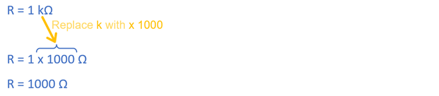
For the sake of making calculations, a common first step is to convert a measurement with a metric prefix to its decimal equivalent. So, instead of starting with 1 kΩ, you’d want to start with 1000 Ω. For this step, just replace the metric prefix with x metric-prefix-decimal-value. If you are not sure of the metric prefix’s decimal value, just look it up in the table.
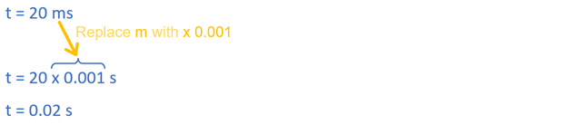
Here is another example with 20 ms. Looking up m in the SI Metric Prefixes table, its decimal value is 0.001. So, replace m with x 0.001, and then calculate the result.
If you multiply some value by 1, the result is that same value. For example, 2 kΩ x 1 = 2 kΩ. The quantity is unchanged. The faction 1000 / k is also equal to the number 1. Remember from the SI Metric Prefix chart that kilo = 1000. So if you start with k = 1000 and divide both sides by k, you get 1000 / k = 1. Multiplying 2 kΩ by 1 (in the form of 1000/k), the k’s in the numerator and denominator cancel, and the result is 2000 Ω. It’s still the same value as 2 kΩ, but in this case, without the metric prefix.
(View full size: muam-multiply-by-one-prefix-to-val.mp4)
This script converts quantities and metric prefixes to the numbers they represent.
Example Script: metric_prefixes_to_values
# metric_prefixes_to_values

prefix_exponents = {'M':6, 'k':3, 'm':-3, 'u':-6}

print("Enter quantity, metric prefix, and unit.")
print("Result will be a decimal value.")
print()

while True:
    text = input("Enter quantity: ")
    quantity = float(text)

    prefix = input("Enter metric prefix: ")
    exponent = prefix_exponents[prefix]

    unit = input("Enter unit: ")

    value = quantity * (10 ** exponent)

    digits = str(abs(exponent) + 1)

    if value < 1:
        fstr = "%." + digits + "f"
    else:
        fstr = "%" + digits + ".0f"

    print("Value:", fstr %value, unit)

    print()
This script converts quantities and metric prefixes to the numbers they represent.
Here are some you will see in upcoming lessons.
The metric_prefixes_to_values script converts quantities and metric prefixes to the numbers they represent.
This script’s first statement is called a dictionary. A dictionary has a name. (prefix_exponents) and key-value pairs (Like ’M’:6 and ’k’:3). The keys are ’M’, ’k’, ’m’, and ’u’. The value paired with ’M’ is 6; the value paired with ’k’ is 3, and so on… Later in the script, a statement will retrieve the value that’s paired with a given key and use it as an exponent. For example 3, will become 1 x 10³. To learn more about dictionaries, try the Dictionary Primer.
prefix_exponents = {'M':6, 'k':3, 'm':-3, 'u':-6}
These are print statements. Each print statement contains a string object, the text between quotes. The one that’s just print() adds an empty line before the next print statement.
print("Enter quantity, metric prefix, and unit.")
print("Result will be a decimal value.")
print()
Inside the endless while True loop, text = input(“Enter quantity: “) displays Enter quantity: and then stores the value you type in a variable named text. quantity = float(text) converts the characters you typed into a floating-point number that the micro:bit can use in statements that make calculations.
while True:
    text = input("Enter quantity: ")
    quantity = float(text)
Another input statement stores the metric prefix you type (like M, k, m, or u) in a variable named prefix. Then, prefix_exponents[prefix] looks up the value that’s paired with that prefix in the dictionary at the beginning of the script. For example, if you typed M, the key is ’M’, so the value that gets returned by prefix_multipliers[prefix] will be 6, and that’s the value that gets stored in the exponent variable. Another example, If you typed k, the key will be ’k’, and the value that gets stored in exponent will be 3. Again, to learn more, try the Dictionary Primer.
    prefix = input("Enter metric prefix: ")
    exponent = prefix_exponents[prefix]
This final input statement just stores a unit you type. Those should be SI units like A, F, Hz, and V. For Ω, substitute ohm.
unit = input("Enter unit: ")
The quantity and exponent variables were set earlier. Quantity is the number you typed in response to the “Enter quantity” prompt like 1 or 20. The exponent variable stores the value from the dictionary. So, when you typed k, it looked up 3 in the dictionary, or when you typed m, it looked up -3. So, if you typed a quantity of 1 and a prefix of k, this would multiply 1 by 1×103 for a result of 1000. If you typed a quantity of 20 and a prefix of m, it would multiply 20 by 1 x 10-3 for a result of 0.02, and so on…
value = quantity * (10 ** exponent)
The script will need a string with a character in it, like ‘4’ for k or m, or ‘7’ for m or u, to help format the value it displays. It starts by taking the absolute value of the exponent. So, regardless of whether the exponent is -3 or 3, the absolute value will be 3. Then, it adds 1 to that value. Then, the value (7 or 4) is converted to a string that contains ‘7’ or ‘4’. The resulting string with the character is stored in a variable named digits.
digits = str(abs(exponent) + 1)
Don’t worry too much about the details of this part; it’s a little more advanced. Scripts can use statements like print(“value %3.2f”, value) to display a total of 3 digits with 2 to the right of the decimal point. These lines in the script build a formatting string like “%3.2f”, but adjusted to the size of the value the script is about to display.
   if value < 1:
        fstr = "%." + digits + "f"
    else:
        fstr = "%" + digits + ".0f"
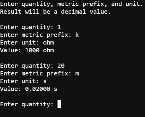
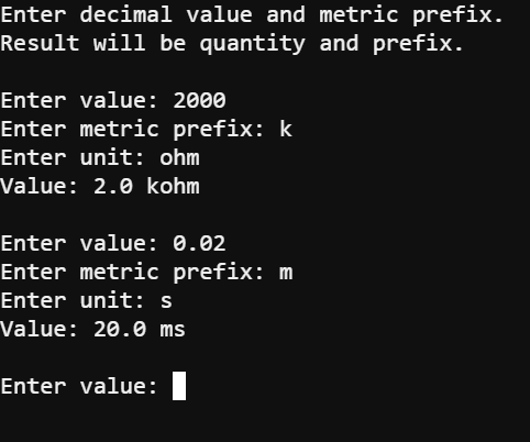
This statement makes the result appear in the Serial Terminal. It prints “Value: ” followed by the specially formatted string that represents the value, followed by the unit. For example, this is what makes 1000 ohm or 0.0200 s appear.
print("Value:", fstr %value, unit)
This prints an empty line before the while True loop repeats and asks you to enter your next quantity.
print()
If you use metric prefixes that are not in the dictionary, such as G, n or p, the script will display a message about an exception.
prefix_exponents = {'G':9, 'M':6, 'k':3,
                    'm':-3, 'u':-6, 'n':-9, 'p':-12}
Again, because of how the micro:bit module’s 32-bit floating point arithmetic works, the results will be slightly different from what you get with a calculator. It’ll be close, but not quite as precise. For example, if you expect 40000000000, you might get something like 39999995231. The result is still more than 99.9999% correct.
After making calculations with the decimal values, for example, you may need to convert back to metric prefixes. Let’s look at how that works.
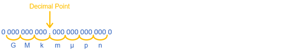
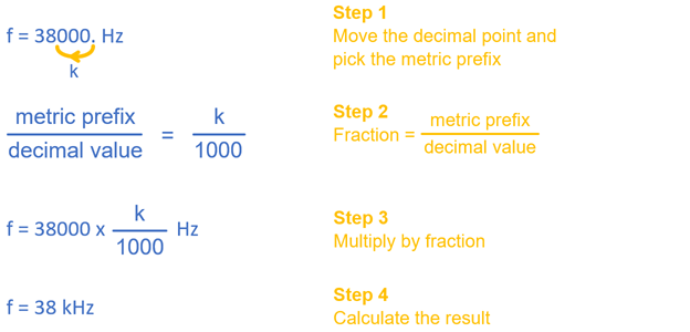
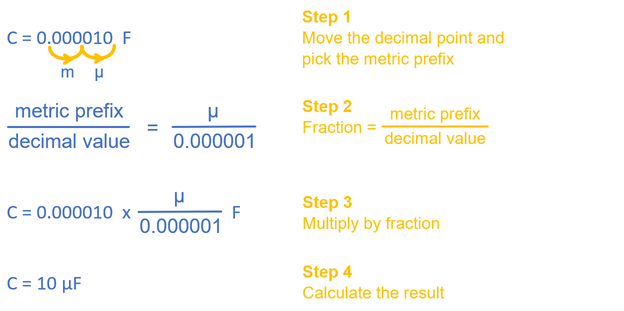
Step 1: Decide how many places to the left or right to shift the decimal point and select the corresponding metric prefix. For example, if you shift it left by 3, that’ll be k (kilo), or if you shift it left by 3 more (for a total of 6), that’ll be M (mega). For shifting to the right, 3 would be m (milli), 6 would be µ (micro), and so on… Tip: Make sure to use multiples of 3.
Step 2: Find the decimal value for the metric prefix in the SI Metric Prefixes table and make a fraction of metric prefix / decimal value.
Step 3: Multiply your quantity by the fraction.
Step 4: Calculate the result.
Example: Convert 38,000 Hz so that it has a metric prefix. Hint: In engineering notation, it’s usually preferable for the integer part of the quantity to be in the 1…999 range.
Here are examples of how metric prefixes change the schematics you’ve been working with. Again, shoot for an integer portion in the 1…999 range.
Remember from earlier, how if you multiply some quantity by 1, the result is that same quantity? The example started with 1000 = k and divided both sides of the equal sign by k for a result of 1 = 1000 / k. You could divide both sides by 1000 instead for 1 = k / 1000. Then, starting with 2000 Ω, you can multiply by k / 1000. The thousands cancel, and the result is 2 kΩ.
(View full size: muam-multiply-by-one-val-to-prefix.mp4)
The scrip values_to_metric_prefixes converts decimal values to quantities with metric prefixes. It is similar to the previous example program, but there are two main differences. First, values_to_metric_prefixes is not using special formatting strings to ensure that the values display as decimal (instead of sometimes displaying exponential notation). Second, this conversion is the inverse of the previous conversion. In this script, the value-to-quantity conversion is done with division:
quantity = value / (10 ** exponent)
In the previous example, the quantity to value conversion was done with multiplication:
value = quantity * (10 ** exponent)
Since 1 x 10³ is 1000, it can also be used in place of the prefix k. This same rule applies to all rows in the SI Metric Prefixes table on this page.. Just remember to use the rules of scientific notation in your calculations!
(View full size: muam-multiply-by-one-sci-note.mp4)
The values_to_metric_prefixes script converts values to quantities with metric prefixes.
# values_to_metric_prefixes

prefix_exponents = {'M':6, 'k':3, 'm':-3, 'u':-6}

print("Enter decimal value and metric prefix")
print("Result will be quantity and prefix.")
print()

while True:
    text = input("Enter value: ")
    value = float(text)
    prefix = input("Enter metric prefix: ")
    exponent = prefix_exponents[prefix]
    quantity = value / (10 ** exponent)
    unit = input("Enter unit: ")
    prefix_unit = prefix + unit
    print("Value:", quantity, prefix_unit)
    print()
This script converts decimal values to quantities and metric prefixes.
Explain how to update the Ohmmeter Parts drawing so that it uses SI units and metric prefixes. Your goal is to keep any quantities in the 1 to 999 range.
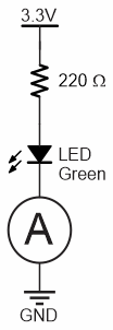
Current, the flow of electrons in a circuit, is measured in amps or amperes. In this activity, you will use an ammeter to measure current through a circuit. The trick to measuring current is that the ammeter needs to be connected in series with the circuit. That way, the same current that flows through the circuit flows through the ammeter to be measured. The circle with the A inside is the schematic symbol for ammeter.
In this activity, you will:
This activity re-uses the setup and LED Circuit parts from Measure Resistance, as well as parts for a second LED circuit and additional resistors for testing.
(2) green LEDs
(2) 220 Ω resistors (red-red-brown-gold)
(2) Jumper wires, black
(1) 1 kΩ resistor brown-black-red-gold
(1) 2 kΩ resistor red-black-red-gold
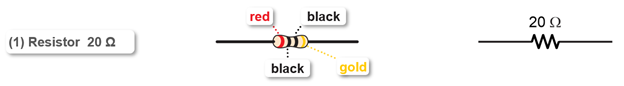
(1) 20 Ω resistor (red-black-black)
The 20 Ω resistor is part of the ammeter. It is important to use the correct one, so look carefully at the color bands so you don’t mix them up! The color code for the 20 Ω resistor is red-black-black-gold:
Rcall that the circuit and procedure for measuring resistance with an ohmmeter was different from measuring voltage with a voltmeter. Measuring current with an ammeter also requires its own circuit and procedure different from the other two.
To start, you will need one LED circuit an the ammeter circuit on your board.
For the current measurement, you have to insert the 20 Ω resistor into the circuit. To do this:
IMPORTANT: Remove the 20 Ω resistor after you are done with current measurements in this activity. It is only needed when measuring current, and it could cause errors in voltage measurements later if it’s not removed.
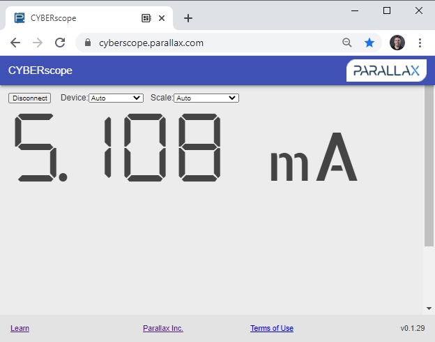
You are now ready to measure current through the LED.
The m in mA is the metric prefix for milli or “1/1000th of”. In this case, the current measurement is 5.108 mA, or 5.108 thousandths of an amp.
The micro:bit, Python script, CYBERscope, 20 Ω resistor, and alligator clip probes all work together to emulate a common multimeter running in ammeter mode. Keep in mind that something akin to the 20 Ω resistor is inside the ammeter. You would not be adding it to the circuit, just connecting the multimeter’s probes in series, just like you did with the alligator clip probes.
The ammeter script’s multimeter module measures the voltage across the 20 Ω resistor by subtracting the voltage measured at P0 from the voltage measured at P2. The multimeter module’s ammeter function then uses I = V / R to calculate current from voltage and resistance. For example, if V is 0.01 V and R is 20 Ω, then I = V / R = 0.01 V / 20 Ω = 0.005 A = 5 mA.
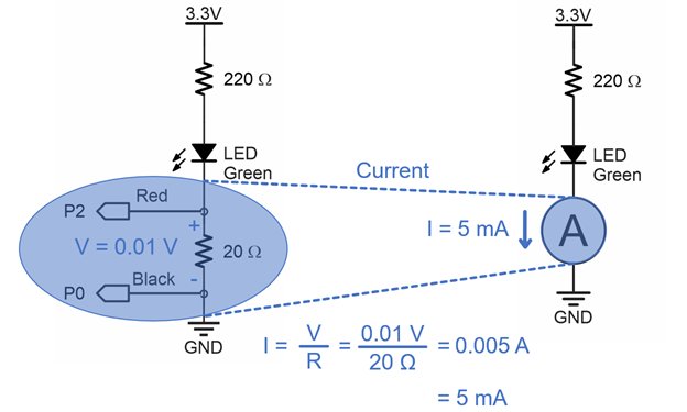
I = V / R is one of the three forms of the Ohm’s law equations, which you will experiment with in the next activity.
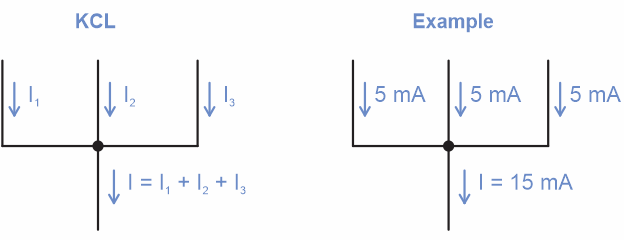
Kirchhoff’s current law (abbreviated KCL):
“For any node (junction) in an electrical circuit, the sum of currents flowing into that node is equal to the sum of currents flowing out of that node.” [1]
For example, if the current from three parallel circuits feeds into a single circuit, the current in that single circuit would be the sum of the three currents. In equation terms, three circuits would be:
I = I1 + I2 + I3
… for some number of n circuits, you’d add all of them up:
I = I1 + I2 + … + In
1. Wikipedia. 2021. “Kirchhoff’s circuit laws.” Wikipedia The Free Encyclopedia.
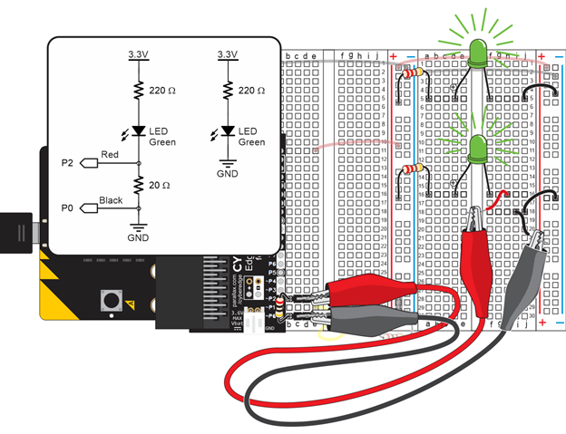
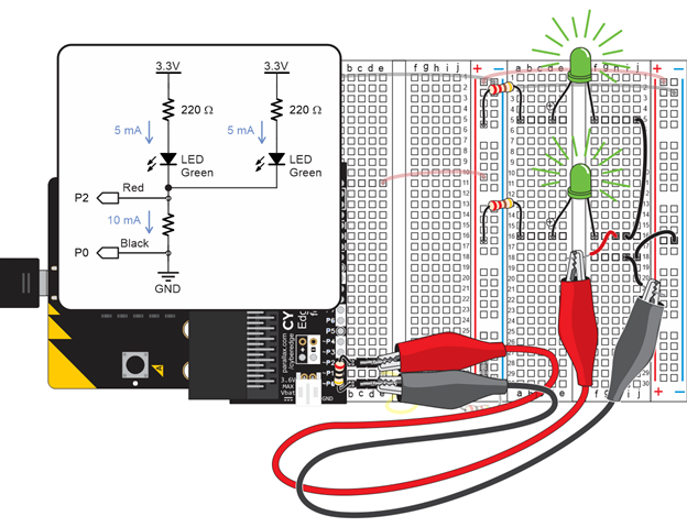
Let’s test Kirchhoff’s current law by verifying the current into a node is equal to the sum flowing out. We can do this by connecting another green LED circuit to the ammeter.
Both LED circuits will conduct about 5 mA. If both of them are connected to ground through the ammeter, the sum of the currents flowing through the 20 Ω resistor should be about 10 mA.
In this activity, you:
Ohm’s law is a mainstay in calculations related to circuits. It doesn’t matter whether the circuit is simple or complex, nor does it matter whether the device is small and battery powered, or large and part of the national power grid. Engineers and technicians often end up using Ohm’s law equations to understand what is happening—or what is supposed to happen—in the circuit.
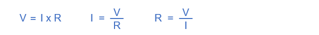
The Ohm’s law equations relate voltage, current and resistance. It’s really just a single equation that can be rearranged one of three ways depending on what unknown you need to solve for:
In this activity, you will:
In this activity, you won’t:
One application of Ohm’s law is calculating current through a resistor from measured voltage. That way, you won’t have to worry about changing the circuit to measure current. Just probe a resistor’s leads for the voltage across it, and then use I = V / R to calculate the current through it.
Take a look at the resistor probed in the circuit below. From previous activities, you know the resistance is 220 Ω and the voltage is 1.20 V.
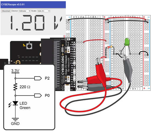
Instead of connecting the circuit to an ammeter, you can just use I = V / R to calculate the current through the circuit since you know that the resistance is 220 Ω and the voltage is 1.20 V. Here’s the calculation:
I = V / R
= 1.20 V / 220 Ω
= 0.0054545… A
≈ 5.46 mA
You can also use Ohm’s law to calculate the smallest resistor to safely use with an LED circuit. Why do that? To get maximum brightness! The LEDs in your kit are rated for up to 20 mA.
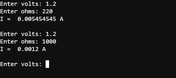
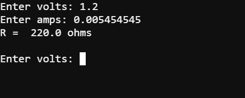
Here is a micro:bit current calculator that you can run to check the current a resistor conducts based on its resistance value and the voltage measured at its leads.
# calculate_i_from_v_and_r

from microbit import *

while True:
    text = input("Enter volts: ")
    V = float(text)
    text = input("Enter ohms: ")
    R = float(text)

    I = V / R

    print("I = ", I, "A")
    print()
The script starts inside the while True loop, prompting you with “Enter volts: “. The characters you type are stored in the text variable. Then V = float(text) converts the characters you have typed from text into a floating point value and stores the result in a variable named V. It repeats those steps for loading the ohms value you enter into the variable R.
while True:
    text = input("Enter volts: ")
    V = float(text)
    text = input("Enter ohms: ")
    R = float(text)
Since V and R are known, the I = V / R form of the Ohm’s Law equation calculates the current value I.
I = V / R
After printing “I = “, the value of I, and the “A” unit, the script prints an empty line. After that, the while True loop repeats so that you can calculate another current value.
   print("I = ", I, "A")
   print()
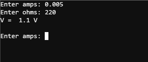
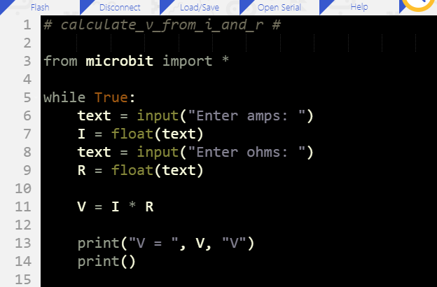
Try modifying your script to calculate volts from amps and ohms.
The various forms of the Ohm’s Law equations are used in many ways. In this section, you will see:
Although there are numerous memory tricks for remembering the versions that solve for I and R, you can also just remember V = I x R and then divide by both sides to isolate either I or R. In other words, if you’re solving for I, divide R into both sides of V = I x R, and the result is I = V / R. Or, if you’re solving for R, divide both sides by I for R = V / I.
(View full size: ol-solve-for-i-or-r.mp4)

Ohm’s Law: “The current through a conductor between two points is directly proportional to the voltage across the two points.”
That translates directly to I = V / R, where (1 / R) is the “directly proportional” constant you can multiply by the voltage to calculate current. Ohm’s law uses the term “two points” to make it more general. Sure, a point at each lead of a resistor is two points, but it can also apply to points on long wires. A long wire, like a power line, has a very small resistance per length. The longer the wire, the greater the resistance.
Earlier, you experimented with changing resistors to make the light dimmer or brighter. The smaller resistors allow more current to flow through the circuit, making the light brighter. One of the goals in a prototype or project, might be to make the light as bright as it can be. This can be done checking the current limitations, then selecting a resistor that will make the circuit conduct the most current within those limitations.
According to the Edge Connector & micro:bit pinout, the V2 module’s 3.3 V supply can source up to 270 mA of current. But, the LED’s maximum current is 20 mA, so that is the limiting factor. So, if you were designing a device and needed the brightest light possible, here is how you would use Ohm’s law to calculate the smallest resistor you can safely use (without damaging the LED by exceeding its current specification).
LEDs have a property called forward voltage, and it changes a little with current, but not much. So let’s assume the voltage drop across it at 20 mA will still be about 2.1 V, like we tested in Measure Voltage. That means, the voltage across the resistor will still be about 1.2 V because they still have to add up to 3.3 V. Again, that’s because Kirchhoff’s voltage law (KVL) says that the voltages across the components have to add up to the voltage of the supply.
R = V / I
= 1.2 V / 0.020 A
= 60 Ω
Important: Only use a resistor that small in an LED circuit if you are drawing power from the 3.3 V and GND rails on your breadboard. A micro:bit I/O pin cannot even supply 5 mA to an LED circuit with a 220 Ω without its voltage sagging.These are rough estimates, and in product designs, derating is often applied to ensure none of the parts ever fail by being too close to their specification maximums or minimums. For example, you might end up repeating the resistor calculations using 15 mA to be on the safe side.
Since the unit for voltage is V, the unit for current is A, and the unit for resistance is Ω, Ohm’s law also tells us how V, A, and Ω relate:
1 A = 1 V / Ω
1 V = 1 A x Ω
1 Ω = 1 V / A
In this activity you:
Modify calculate_i_from_v_and_r.hex so that it displays the result in milliamps.
Solution: The result of I needs to be multiplied by 1000 before it is displayed, and the A unit needs to be updated to mA. Retest the numbers in the activity, and verify that the results are 5.4545… mA and 1.2 mA.
# calculate_i_in_ma_from_v_and_r

from microbit import *

while True:
    text = input("Enter volts: ")
    V = float(text)
    text = input("Enter ohms: ")
    R = float(text)

    I = V / R
    I = I * 1000                   # <-- Add

    print("I = ", I, "mA")         # <-- Modify
    print()