In the circuit you just built, a wire connects A/D2 to the row where the phototransistor’s emitter and resistor meet. The voltage at this part of the circuit will change as the light level sensed by the phototransistor changes. The phototransistor_voltage script measures the voltage at A/D2— one of the micro:bit module ’s three analog to digital input channels—and scrolls that value on the micro:bit module’s display. You will use this sketch to take and write down voltage readings of the ambient light, shade cast by your hand, and optionally of bright light from a flashlight if you have one handy.
Example script: phototransistor_voltage
# phototransistor_voltage

from cyberbot import *

while True:
    ad2 = pin2.read_analog()
    volts = ad2 * (3.3/1024)
    out = "volts = " + str(volts) + "V"
    display.scroll(out, 80)
    sleep(500)
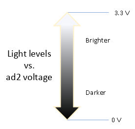
Measurements will vary with ambient light levels, but in general, brighter measurements will tend toward 3.3, and darker ones will tend toward 0 V. If you point the phototransistor at the sun or a bright flashlight, the measurements should be close to 3.3 V. As you block the light and cast darker shade, the measurements should decrease.
Once you have a resistor value in place that works well for differentiating ambient light and shade in your area, you are ready for the next step.
