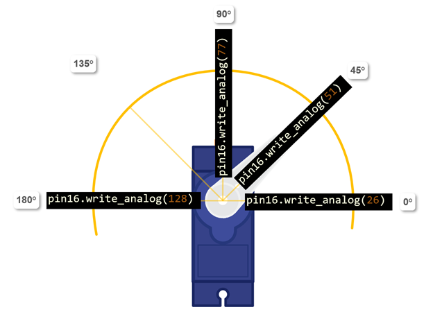
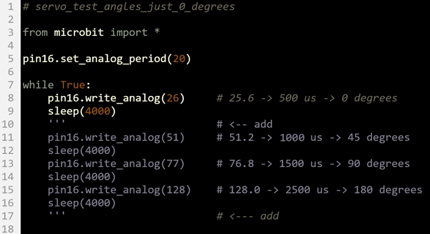
If you are focusing on code to control the servo, pin16.set_analog_period(20) sets up the servo signal, and then pin16.write_analog(value) sets the servo’s position. For the servo, value has to be in the 26 to 128 range, and the resulting angle is in the 0° to 180° range.
Let’s take a closer look. The pin16.set_analog_period(20) statement tells the micro:bit to get ready to repeatedly set P16 high some fraction of 20 ms, and low for the rest of the time.
pin16.set_analog_period(20)
After that, a statement like pin16.write_analog(value) sets the pin high for value/1024ths of that 20 ms, and low the rest of the time. The signal that tells the servo what position to hold is like having a light that blinks at 50 Hz. Fifty LED blinks per second would be too fast for the human eye to discern, but a signal that would make a light blink that fast is what the servo needs for position information. Also, the on-times that actually tell the servo what direction to point are in the 0.5 ms to 2.5 ms range. It’s already impossible for the human eye to discern 50 blinks per second, but to tell the difference between on for 0.5 ms and on for 2.5 ms… Well, the LED would appear to be dim with 2.5 ms high times, and even dimmer with 0.5 ms high times.
The servo control signal the micro:bit script sends via P16 might not be easy for us to decipher, but it contains the position information the servo needs. Here are examples of the on/off signals plotted over time, and how they affect the servo’s position. As you will soon see, the results are not exactly the 0.5, 1.0, 1.5 and 2.5 ms values shown in the animation (See the mp4 here [1]).
Servo signal specifications assume the period of the signal is 20 ms, and then they equate an on-time to a servo position. For this micro-servo, an on time of 0.5 ms results in 0°, an on time of 1.5 ms results in 90°, and an on time of 2.5 ms results in an angle of 180°.
Remember from On-Off Signals [2] that a repeating on/off signal has a period T = tHIGH + tLOW. It also has a percent duty cycle of %DC = tHIGH / (tHIGH + tLOW).
The pin16.set_analog_period(20) call sets the period to 20 ms. That's T = tHIGH + tLOW = 20 ms.
The pin16.write_analog(value) sets the duty cycle as 1024ths of 20 ms. So, the signal high or on time works out to this:
tHIGH = value x 20 ms / 1024.
Example: What’s the actual high time from pin16.write_analog(26)?
Solution:
tHIGH = value x 20 ms / 1024
= 26 x 20 ms / 1024
≈ 0.508 ms
( close to 0.5 ms)
Example: What’s the actual high time from pin16.write_analog(51)?
Solution:
tHIGH = value x 20 ms / 1024
= 51 x 20 ms / 1024
≈ 0.996 ms
( close to 1.0 ms)
Keep in mind this high time is not just one pulse (blink). It is repeated 50 times per second. These repetitions continue while the servo is moving to its new position, and also to make the servo hold its position against opposing forces after it reaches its new position.
Tuning the angles takes three steps. First, make sure the horn is aligned as closely as possible to 0° when the script positions it there. Second, adjust the script to improve 0° alignment. Third, adjust the script to improve the accuracy of the other positions.

Links
[1] https://learn.parallax.com/sites/default/files/content/Python/servo/servo-connect-how-servo-sig-xfer-funct.mp4
[2] https://learn.parallax.com/tutorials/language/python/led-lights/connect-and-blink-light/signals