A hobby servo is normally used to hold the positions of radio controlled model airplane flaps, boat rudders, and car steering. A micro servo is one of the smallest versions of hobby servos. Hobby servos also come in continuous rotation versions which can be used to drive wheels of rolling robots, but the one in your kit is the standard variety that turns to and holds a position.
In this activity, you will:
- Identify a servo’s major parts.
- Connect battery power and a servo to your breadboard.
- Write scripts to control which positions the servo holds.
The servo comes with several different shapes of “horns”. When the servo is built into a radio controlled model boat/airplane/car, screws and linkages connect a horn to the rudder, flap, or steering. Screws go through the mounting flanges to attach the servo’s case to the body or frame of the model plane/boat/car.
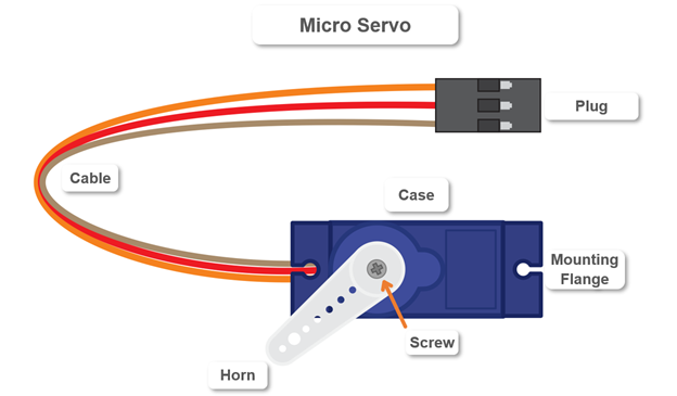
The servo is connected to supply voltage and a control signal through the plug and cable. The control signal, which the micro:bit will send, tells the servo what angle to point the horn. Last but not least, since the horn needs to stay connected to the servo’s output shaft, a screw holds the two together.
Parts
(1) Resistor - 220 Ω (red-red-brown-gold)
(1) Jumper wire - Red
(1) Jumper wire - Black
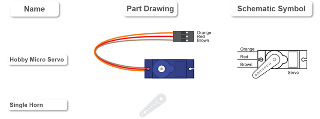
New parts shown in image below:
(1) Hobby micro servo
(1) Single horn
(1) Battery holder
We will not be using a screw to attach the horn to the output shaft in these activities. (If you end up using the servo to move a light load, use the screw that came with it to cinch the horn to the output shaft at that point. )
Assembly & Circuit
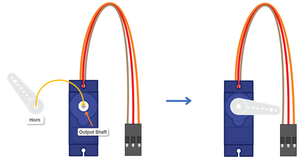
The servo has built-in motion limiters that allow it about a 200° range of motion. Follow these steps to mount the servo horn so that 200° of motion allows the horn to point from 190° to -10° (with 90° being the halfway point).
- Press the single horn onto the servo’s output shaft.
- Gently rotate the horn clockwise until you feel it press against the servo’s built-in motion limiter. (DO NOT TRY TO FORCE IT PAST THAT POINT.)
- Pull the horn back up and off the output shaft
- Orient the servo’s case so that it matches the picture, and press the horn back down so that it points to the right, just a little below level.
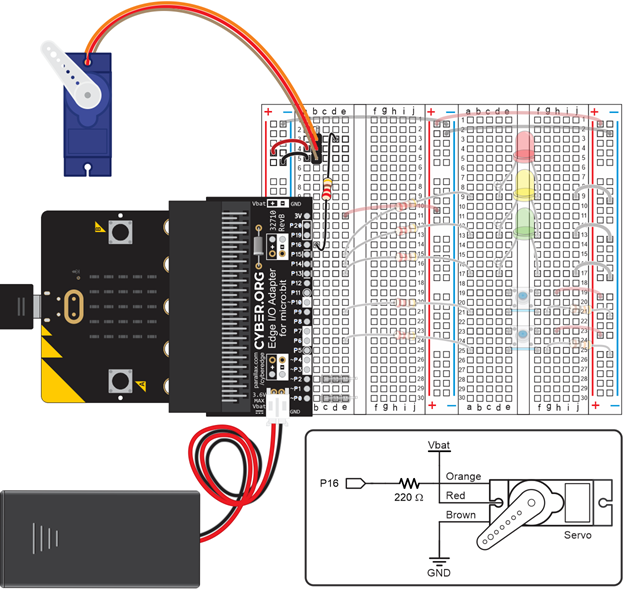
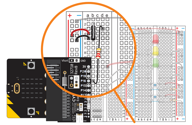
The first step to connecting the servo is to build a servo port. The port needs to connect to power, ground, and a micro:bit I/O pin so the servo can receive a control signal.
- Disconnect the battery pack from the Edge Connector for micro:bit.
- Plug the 3-pin header into the left terminal strip’s column b, rows 3, 4, and 5.
- Use the red jumper wire to connect one of the left bus strip’s (+) sockets to row 4.
- Use the black jumper wire to connect one of the left bus strip’s (-) sockets to row 5.
- Use the 220 Ω resistor to connect the Edge Connector’s P16 pin to row 3.
Next, you will connect the servo to the port. The servo’s three wires need to be connected as follows:
- orange to P16 for signal
- red to (+) for 3 V battery supply
- brown to (-) for common ground
- Line up the holes in the servo plug with the 3-pin header so that the:
- Socket connected to the orange wire is over row 3
- Socket connected to the red wire is over row 4
- Socket connected to the brown wire is over row 5
- Slide the plug onto the 3-pin header. The pins should sink all the way into the plug’s holes.
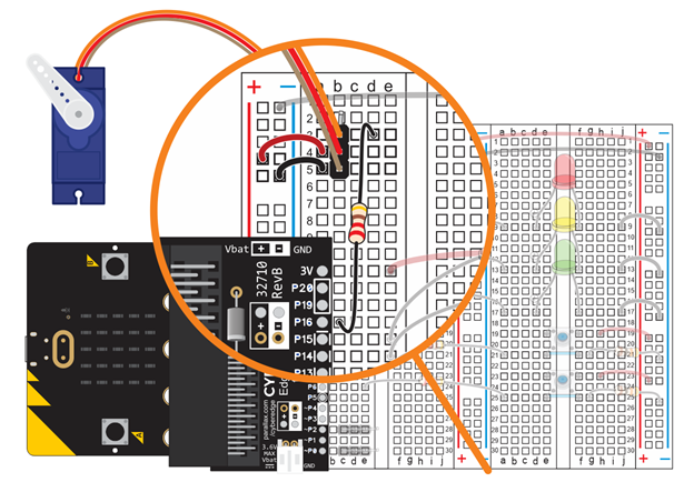
- Connect the battery pack to the Edge I/O Adapter.