The tests you just completed helped verify two things:
The 5 ms/div setting is fine for measuring the servo signal’s period, but a smaller Time/Div setting would be better for measuring the actual pulse width times. Look forward to that in the Try This section.
Here is an excerpt from the servo_plot script:
    pin16.write_analog(51)      # 51.2 -> 1000 us -> 45 degrees
    plot_servo(ch2="servo", delay=40)
    sleep(4000)
The pin16.write_analog(51) and sleep(4000) statements are from the original servo_test_angles script you used to test the servo in Connect and Test the Servo [1]. The plot_servo(ch2=”servo”, delay=40) function call tells the multimeter module to measure a servo signal with the Ch2 probe connected to P2 but wait 40 ms before starting the measurement. This delay in taking the measurement ensures that the micro:bit has successfully switched from whatever servo signal it was sending previously to the new one.
Unlike a real oscilloscope, which would record thousands of voltage measurements and plot them, the multimetermodule measures the servo signal’s high and low times, in microseconds. It uses those measurements to generate a list of voltages and times that it sends to the CYBERscope to emulate what a real oscilloscope does.
A smaller Time/Div setting will make it easier to measure the servo pulses.
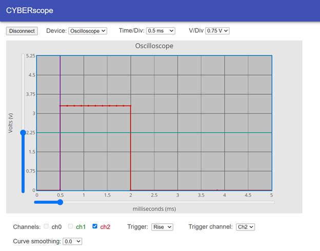
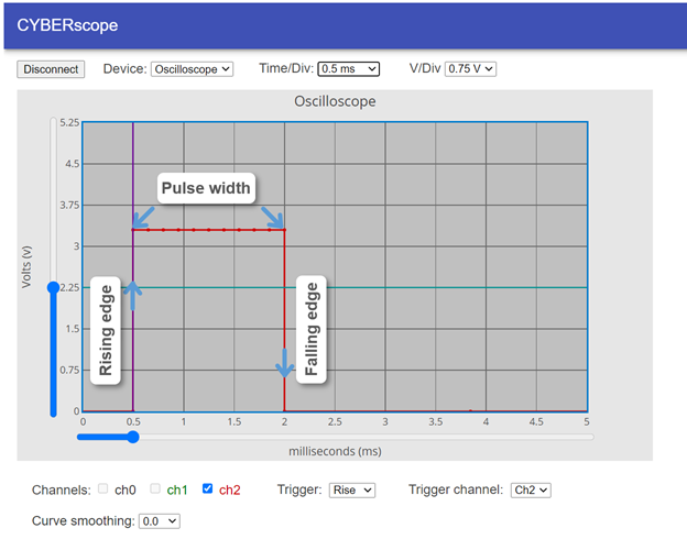
One approach to measuring pulses with an oscilloscope is to subtract the time the pulse’s rising edge occurs from the time the falling edge occurs. In the case of the pulse for 90°, subtract 0.5 ms from 2 ms for a result of 1.5 ms.
Angle Pulse width
0°
45°
90° 2 ms - 0.5 ms = 1.5 ms (Example)
180°

Links
[1] https://docs.google.com/document/d/15auxYUR0YnEvQtKc6jFfm2a4BNcgdhoQRcPrR9eYj_Y/edit#heading=h.ov44fqdkdi74