Measuring Servo Signal with an Oscilloscope
In earlier animations, you have seen how the write_analog(value) function calls make the micro:bit send repeating on/off (or high/low) signals to the servo. The servo positions its horn at an angle in response to how long the ‘on’ part of the signal stays on. These signals can be measured with the CYBERscope’s oscilloscope and compared to how this document said it’s supposed to work.
This kind of activity is the sort of thing students find themselves doing to make sure their motor will run properly before it’s connected. Engineers also do this to verify that their prototypes are running properly, and technicians often take similar measurements when a device with motors isn’t running properly and needs to be diagnosed and fixed.
In this activity, you will:
- Measure a servo signal’s period.
- Calculate its frequency.
- Verify that pulse width (how long the brief on-times last) is what contains the information the servo needs to respond to by correctly positioning its horn.
- Predict a pulse width at a certain angle and write a script to:
- Set the servo to that angle
- Test to verify that your predicted pulse width is correct
Parts
Same as previous activity + red alligator clip and jumper wire.
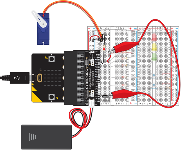
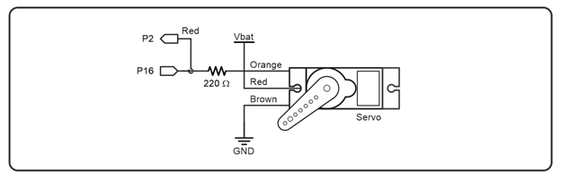
Circuit
We’ll be using the P2 red alligator clip lead to monitor signals the micro:bit sends to the servo.
- Connect the red alligator clip lead from the 3-pin header at P2 to the same row as the servo’s orange signal wire. As shown, it’s connected to (e, 14).