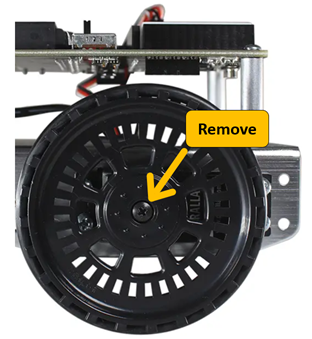
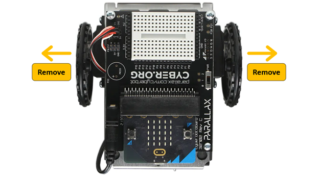
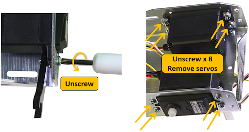
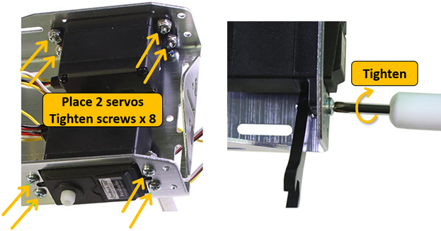
In this activity, you will remove the cyber:bot robot’s existing continuous rotation servos and replace them with Feedback 360° servos.
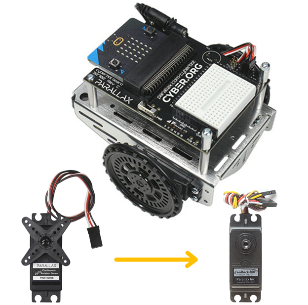
(1) Fully assembled cyber:bot robot. See Build your cyber:bot (Rev C Board) [1].
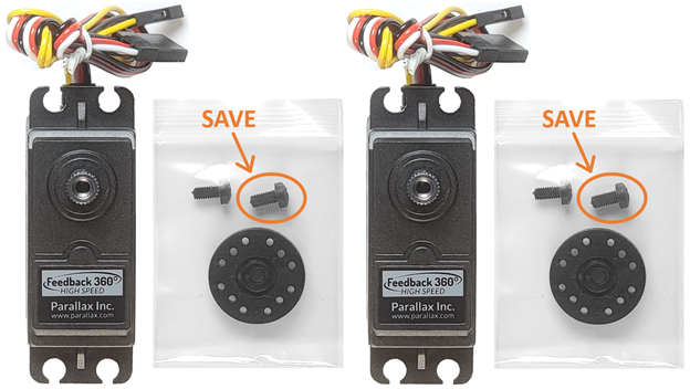
(2) Parallax Feedback 360° servos (#900-00360) [2]
(1) Parallax Screwdriver that comes with the cyber:bot (#700-00064)

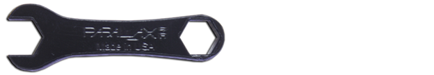
(1) Plastic combination wrench that comes with the cyber:bot (#700-10025)
IMPORTANT: Do not throw away any of the parts you remove from the cyber:bot. You will be reattaching them later.
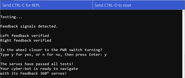
This script tests if the electrical connections between the Feedback 360° servos and the cyber:bot board are all correct.
cyberbot_feedback_360_diagnostic.hex [3]
These tests — and any wiring corrections you may need to do — will need to be repeated until you see the “The servos have passed all the tests!” message.
There are several different types of error messages. Find the one you see in the sections below, and follow the red checkmarks under it to correct the issue.
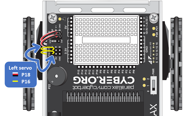
No feedback signal to P16.
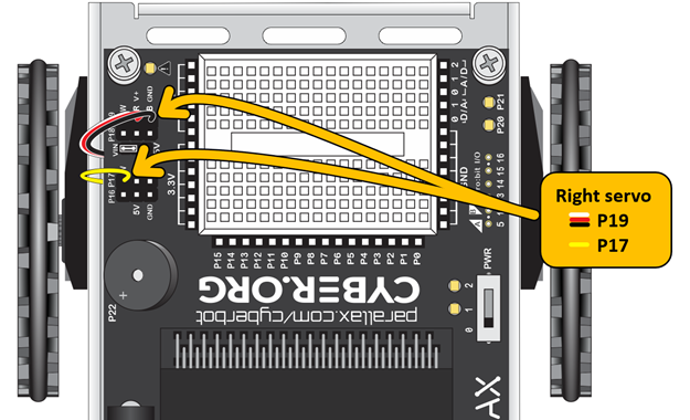
No feedback signal to P17.
Problem with feedback signal(s).
If you see all three feedback messages:
If you only see two of the three messages listed above, use the Circuit section as a reference and try these:
If there’s no feedback signal to P16:
If there’s no feedback signal to P17:
Either yellow wires are swapped with each other
or servo cables are swapped with each other.
If you see this message:
The wheel closer to the PWR switch should be turning.
If you see this message:
It means that the yellow wires are swapped with each other, AND the servo cables are swapped with each other.
The servo connected to P18 does not seem to be turning.
The servo connected to P19 does not seem to be turning.
If you see this message:
The servo connected to P18 is turning too slowly.
The servo connected to P19 is turning too slowly.
If you see this message:
The P18 servo is turning unusually fast.
The P19 servo is turning unusually fast.
If you see this message:
print('The P18 servo is turning unusually fast.')
print('The P19 servo is turning unusually fast.')
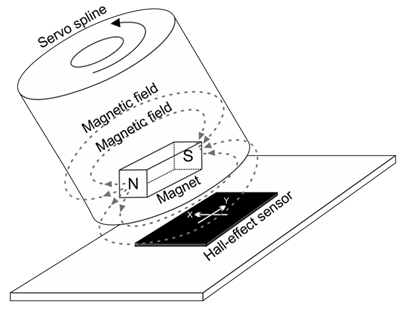
An encoder converts information from one format to another.
Each Feedback 360° servo has a tiny magnet inside that is attached to the motor shaft. Also inside the servo's case is a Hall-effect sensor, which can detect changes in the position of the magnetic field as the motor shaft rotates. A tiny processor monitors the Hall-effect sensor and converts it to position information which is then sent to the Propeller I/O pin. (For more details, see the Feedback 360° Servo product guide, which is a download from the #900-00360 product page at www.parallax.com.)
Throughout this tutorial, you will see the term "ticks" when used to describe the cyber:bot's wheels turning. In this context, a tick means 1/64th of a wheel revolution. This name is a carry-over from an older style of external optical wheel encoders that watched each wheel spoke go by. When the wheel makes one complete revolution, it has turned 64 ticks. We use ticks per second to note how fast the wheels are turning. Ticks can also refer to distance traveled, when considering the circumference of the cyber:bot wheel.

Links
[1] https://learn.parallax.com/tutorials/robot/cyberbot/build-your-cyberbot-rev-c-board
[2] https://www.parallax.com/product/parallax-feedback-360-high-speed-servo/
[3] https://learn.parallax.com/sites/default/files/content/cyberbot/F360/cyberbot_feedback_360_diagnostic.hex
[4] https://python.microbit.org/v/2