Connect and Test the Ping))) Distance Sensors
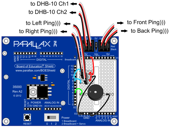
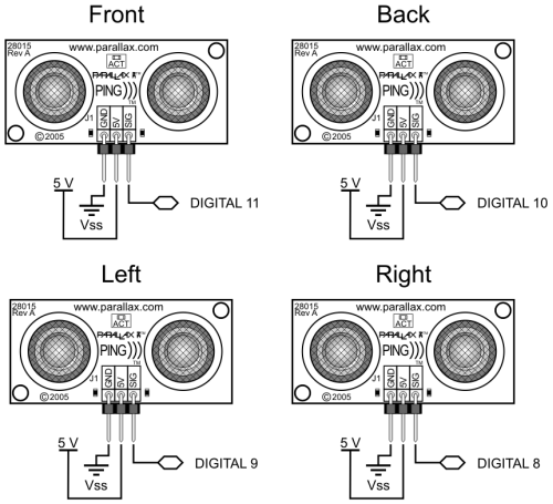
The diagram below shows where to connect each 3-wire Ping))) sensor cable. If you’re looking at the color version, note that each black wire is connected to either GND on the breadboard, or the GND terminal in the servo header (labeled Black to the right of the header block). Each of those black wires should also be connected to a Ping))) sensor’s GND pin.
IMPORTANT: The power jumper between BOE Shield servo ports 11 and 12 should also be set to 5V.
WARNING: Wiring errors can damage the Ping))) sensors and/or your Arduino. Do not turn power back on until you have double-checked all the connections in this section’s checklist below.
- Turn all power off before building the circuit.
- Double check to make sure the power jumper between the 11 and 12 servo ports is set to Vdd (5 V).
- Make sure that each 3-wire cable’s black wire is connected to a Ping))) sensor’s GND connection (and red to 5 V and white to SIG).
- On the BOE Shield’s breadboard, make sure that each 3-wire cable’s black wire is connected to GND, each red wire is connected to 5 V, and each white wire is connected to its corresponding I/O pin: DIGITAL 9 to the front Ping))) sensor, and DIGITAL 8 to the back.
- In the BOE Shield’s servo header, make sure that the front Ping))) sensor is connected to P11 and back to P10. Then, double check to make sure that all black wires in the servo ports align with the Black label to the right of the servo port block.


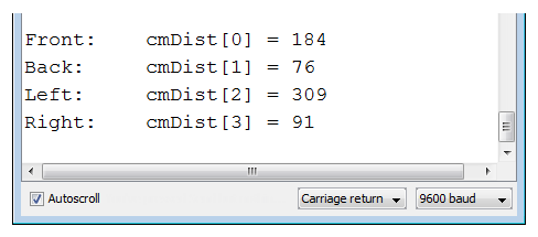
The Terminal display after connecting the Ping))) sensors and running the example sketch will resemble this. If all the Ping))) sensors are connected correctly, the display should show the centimeter distances of obstacles placed in front of each one (within its 3 cm to 3 m range, and typically good to +/- 1 cm).

In the terminal, the right left Ping))) sensor does not see an obstacle, either because it’s beyond the 3 m limit, or the obstacle might be at an angle that’s reflecting the ultrasonic energy away from (instead of back to) the sensor. If you put your hand about 10 cm in front of the right sensor, that value should change to about 10. Make sure that each sensor correctly reports distances when you do that.
- Upload Test Ping Array.ino.
- Use the Terminal and an obstacle (like your hand) 10 cm from each sensor to verify that each Ping))) sensor correctly reports centimeter distances of obstacles you place in front of them.
- For any Ping))) that doesn’t respond correctly, check the wiring connections.
/*
  Arlo-Test-Ping-Sensors
*/

String directions[4] = {"Front:    ",         // Directions for display
                        "Back:     ",
                        "Left:     ",
                        "Right:    "};
int pingPin[4] = {11, 10, 9, 8};              // Ping pins
int cmDist[4];                                // Cm distances
int i = 0;                                    // Index, stat at 0

void setup()                                  // Setup function
{
  Serial.begin(9600);                         // Start terminal communication
}

void loop()                                   // Main loop
{
  cmDist[i] = pingCm(pingPin[i]);             // Get distance

  Serial.print(directions[i]);                // Display direction
  Serial.print("cmDist[");                    // Display variable name
  Serial.print(i);                            // Display variable index
  Serial.print("] = ");                       // Display ] & =
  Serial.println(cmDist[i]);                  // Display value
  i++;                                        // Increase index by 1
  if(i == 4)                                  // If index is 4
  {
    i = 0;                                    // Reset index to 0
    delay(1000);                              // Wait a second
    Serial.println();                         // Print a blank line
  }
}

int pingCm(int pin)                           // Ping measurement function
{
  digitalWrite(pin, LOW);                     // Pin to output-low
  pinMode(pin, OUTPUT);
  delayMicroseconds(200);                     // Required between successive
  digitalWrite(pin, HIGH);                    // Send high pulse
  delayMicroseconds(5);                       // Must be at least 2 us
  digitalWrite(pin, LOW);                     // End pulse to start ping
  pinMode(pin, INPUT);                        // Change to input
  long microseconds = pulseIn(pin, HIGH);     // Wait for echo to reflect
  return microseconds / 29 / 2;               // Convert us echo to cm
}
