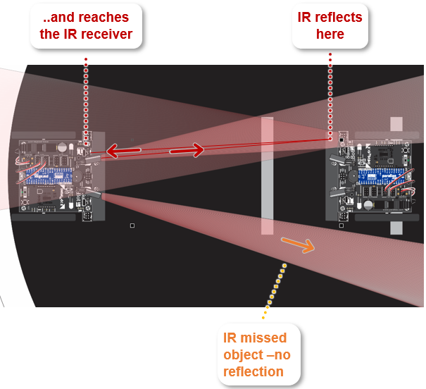
If humans could see infrared as red, it might look like the image below. The SumoBot on the left shines both of its IR lights. The lower beam misses the opponent SumoBot, and just keeps going. In this case, the IR receiver sends a high signal to the Propeller microcontroller’s P6 I/O pin because it does not detect any infrared. The upper beam bounces off the corner of the opponent SumoBot, and some of the reflected infrared light reaches the IR receiver connected to P5. That IR receiver sends P5 a low signal indicating it detected infrared light.
Let's take a look at the SumoBot-Front-IR-Terminal code blocks.
The main loop just repeatedly calls two functions with run function blocks. First, it calls "IR Front" to measure the distances, and then "IR Front Terminal" to display those distances.

The program contains all the functions you have created up until now as well as a few new ones. For example, QTIs front Turn from Border is new, and if you look inside, you’ll see the switch...case statement you created to avoid the border in Navigate with QTIs -Avoid the Border. The IR Front function is also new, and it does the IR measurement work.
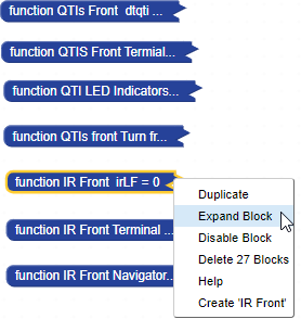
- Right-click the function IR Front block, and select Expand block.
When you expand the IR front block, it should look like this.
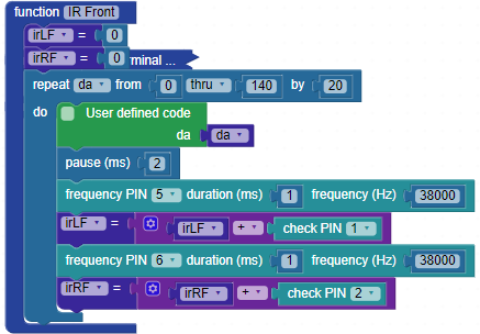
The IR front block uses frequency PIN 5 duration (ms) 1 frequency (Hz) 38000 to make the IR LED flicker on/off at 38,000 Hz (times per second). This is what the IR receiver requires to detect the reflected infrared. Other sources of infrared, like lamps and sunlight, do not tend to flicker at 38,000 Hz—they’re usually emitting infrared at some constant level instead of flickering. This consistent, rapid on/off behavior makes it possible for the IR receivers in devices to detect the signal from an IR remote by only detecting infrared that flickers at 38,000 Hz.
Immediately after making the IR LED flicker for 1 ms, the program uses irLF = irLF + check PIN 1 to check the IR receiver’s output and keep a tally of how many times the object was not detected. In the case of not detected, the IR receiver’s output stays high, and check PIN returns a binary 1. If reflected IR is detected, the IR receiver’s output sends a low signal, and check PIN returns a binary 0.
The process for both IR LEDs and receivers is repeated in a loop that counts from 0 to 140 in steps of 20. The user defined code uses the da variable to set the voltage at all the IR LED’s cathodes. By increasing this voltage, it makes the IR LED dimmer each time through the loop, which in turn makes the IR sensor more nearsighted. By counting the number of times check PIN returns 1 (did not detect an object), it arrives at a number that indicates the relative distance.
When the object is up close, every time through the loop, check PIN returns 0 because no matter how nearsighted it gets, the reflection is still detected. When the object is out of range, check PIN returns 1 each time since it did not detect the flickering infrared reflected off any objects. All those 1 values are added up with the irLF = irLF + check PIN… operation, for a result of 8.