In this activity, you will build and test indicator LEDs that will tell you if an object is detected without the help of the Serial Monitor. This is handy if you are not near a PC or laptop, and you need to troubleshoot your IR detector circuits.
You will also write a sketch to “sniff” for infrared interference from fluorescent lights. Some fluorescent lights send signals that resemble the signal sent by your infrared LEDs. The device inside a fluorescent light fixture that controls voltage for the lamp is called the ballast. Some ballasts operate in the same frequency range of your IR detector, causing the lamp to emit a 38.5 kHz infrared signal. When using IR object detection for navigation, ballast interference can cause some bizarre BOE Shield-Bot behavior!
Adding LED Indicator Circuits
LED indicator circuits are similar to the ones you used with the whiskers. Make sure to be careful about your cathodes and anodes when you connect them.
Parts List
(2) Red LEDs
(2) Resistors, 220 Ω (red-red-brown)
(misc) Jumper wires
- Disconnect the programming and power cables.
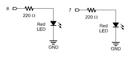
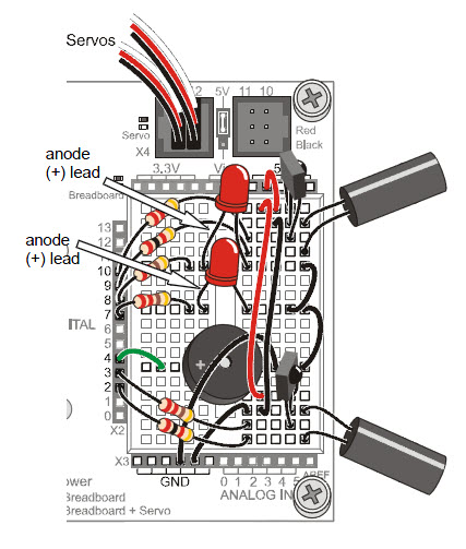
- Add the red LED circuits shown in the schematic to the BOE Shield, using the wiring diagram to help with parts placement.
Testing the System
There are quite a few components involved in this system, and this increases the likelihood of a wiring error. That’s why it’s important to have a test sketch that shows you what the infrared detectors are sensing. Use this sketch to verify that all the circuits are working before unplugging the BOE Shield-Bot from its programming cable.
Example Sketch – TestBothIrAndIndicators
- Reconnect the programming and power cables, and set the Power switch to 1.
- Enter, save, and upload TestBothIrAndIndicators into the Arduino.
- Verify that the speaker makes a clear, audible tone after the upload.
- Use the Serial Monitor to verify that the Arduino still receives a zero from each IR detector when an object is placed in front of it.
- Verify that when you place an object in front of the left IR detector, the left (pin 8) red LED lights up.
- Repeat that test for the right IR detector and pin 7 LED.
/*
 * Robotics with the BOE Shield – TestBothIrAndInciators
 * Test both IR detection circuits with the Serial Monitor.  Displays 1 if
 * the left IR detector does not detect an object, or 0 if it does.
 * Also displays IR detector states with indicator LEDs.
 */

void setup()                                 // Built-in initialization block
{
  tone(4, 3000, 1000);                       // Play tone for 1 second
  delay(1000);                               // Delay to finish tone

  pinMode(10, INPUT);  pinMode(9, OUTPUT);   // Left IR LED & Receiver
  pinMode(3, INPUT);  pinMode(2, OUTPUT);    // Right IR LED & Receiver
  pinMode(8, OUTPUT); pinMode(7, OUTPUT);    // Indicator LEDs

  Serial.begin(9600);                        // Set data rate to 9600 bps
}

void loop()                                  // Main loop auto-repeats
{
  int irLeft = irDetect(9, 10, 38000);       // Check for object on left
  int irRight = irDetect(2, 3, 38000);       // Check for object on right

  digitalWrite(8, !irLeft);                  // LED states opposite of IR
  digitalWrite(7, !irRight);

  Serial.print(irLeft);                      // Display 1/0 no detect/detect
  Serial.print("  ");                        // Display 1/0 no detect/detect
  Serial.println(irRight);                   // Display 1/0 no detect/detect

  delay(100);                                // 0.1 second delay
}

// IR Object Detection Function

int irDetect(int irLedPin, int irReceiverPin, long frequency)
{
  tone(irLedPin, frequency, 8);              // IRLED 38 kHz for at least 1 ms
  delay(1);                                  // Wait 1 ms
  int ir = digitalRead(irReceiverPin);       // IR receiver -> ir variable
  delay(1);                                  // Down time before recheck
  return ir;                                 // Return 1 no detect, 0 detect
}
Inside TestBothIrAndIndicators
After the two calls to the irDetect function, irLeft and irRight each store a 1 if an object is not detected, or 0 if an object is detected. The sketch could have used an if…else statement to turn the indicator lights on/off depending on the value of irLeft and irRight. But, there are other ways!
This approach uses the values of irLeft and irRight directly. There’s only one catch: when (for example) irLeft stores 0, we want its red indicator LED to turn on, and if it stores 1, we want its LED to turn off. Since 1 makes the indicator LED turn on and 0 turns it off, using digitalWrite(8, irLeft) would give us the opposite of what we want. So, the sketch uses the not operator (!) to invert the value that irLeft stores. Now, digitalWrite(8, !irLeft) inverts the value of IrLeft so that when it stores a zero, the LED turns on, and when it stores 1, the LED turns off. The same technique is applied for the right IR detector and indicator LED.
The Not (!) Operator inverts all the binary values in a variable.
There’s more going on with digitalWrite(8, !irLeft) here than meets the eye. You’re probably used to passing the digitalWrite function’s value parameter either HIGH (constant for 1) to turn the light on, or LOW (constant for 0) to turn the light off. When you use variables, the digitalWrite function uses the variable’s rightmost binary digit: 1 to turn the light on, or 0 to turn the light off. So, when irLeft is 0 (object detected) !irLeft changes its binary value 00000000 to 11111111. It has a 1 in the rightmost digit, so the light turns on. When irLeft is 1, it’s really binary 00000001. The !irLeft statement results in binary 11111110. Rightmost digit is 0, so the light turns off.
Your Turn – Remote Testing and Range Testing
With the indicator LEDs working, you can now unplug the BOE Shield-Bot from its programming cable and test detection with a variety of objects. Since certain objects reflect infrared better than others, the IR object detectors will be able to see some objects further away, and others only when very close.
- Make sure the battery pack is connected to your Arduino and the BOE Shield’s Power switch is set to 1.
- Unplug your BOE Shield-Bot from the programming cable, and test again with objects in the area where you plan to make it navigate.
- Test the detection range with different colored objects. What colors and surfaces can it detect only at closest range? What colors and surfaces can it detect from farther away?