Many items you use every day have pushbuttons. Cell phones, microwave ovens, TV remotes, and computer keyboards might all have pushbuttons.
Here we introduce a common pushbutton circuit and a program for monitoring it with your microcontroller. It also shows how to use a pushbutton's state to control LED light circuits. Keep in mind that lights are just one example of a device you can turn on and off with a microcontroller. Your invention might instead use pushbuttons to control circuits for motors, heating elements, or other devices.
Circuit
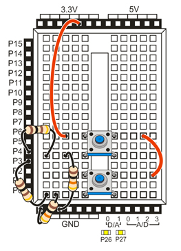
This circuit uses the same P26 and P27 LEDs on the Propeller Activity Board or FLiP from Blink a Light, along with two pushbutton circuits you will build onto your breadboard.
Parts
(2) pushbuttons (#400-00002)
(2) 100 ohm resistors (brown-black-brown) or (2) 220 ohm resistors (red-red-brown)
(2) 10 k-ohm resistors (brown-black-orange)
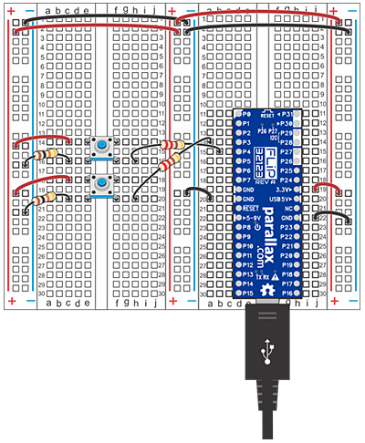
If you don't have 100 ohm resistors, switch them out for 220 ohm resistors (red-red-brown) when setting up your circuit. The Activity Board diagram shows 100 ohm resistors, the FLiP breadboard shows 220 ohm resistors.
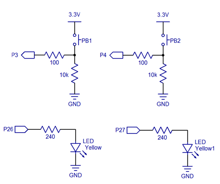
- Build the two pushbutton circuits shown here on your breadboard.
Note: Use the schematics with any Propeller board that has a prototyping area. This activity will not work with the resistive touch-buttons on the Propeller QuickStart.
Test Code
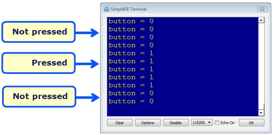
This example will display the state of the button connected to P3 in the SimpleIDE Terminal. It displays 1 if the button is pressed, or 0 if it is not pressed.
- Click the Open Project button.
- Open Button Display from …\Documents\SimpleIDE\Learn\Examples\Circuits.
- Set the power switch to position 1 (if applicable for your board).
- Click the Run with Terminal button.
- Watch the display as you briefly press and release the pushbutton.
How it Works
The pushbutton circuit: When the pushbutton is not pressed, the circuit applies GND (0 V) to the I/O pin. If the pushbutton is pressed, the circuit applies 3.3 V to the I/O pin, and a small amount of current passes from the 3.3 V connection, through the 10 kΩ resistor to ground. Setting P3 and P4 to input lets the I/O pins monitor the voltages on the pushbutton circuits while remaining invisible to them.
The code: The simpletools library’s input function returns 1 if the button is pressed, or 0 if it is not pressed. int button = input(3) copies the result to a variable named button. Then, pause(100) delays for 1/10 of a second before repeating the while(1) loop.
/*
  Button Display.c

  Displays the state of the P3 button in the SimpleIDE Terminal.
  1 -> button pressed, 0 -> button not pressed.
*/

#include "simpletools.h"                      // Include simpletools

int main()                                    // main function
{
  while(1)                                    // Endless loop
  {
    int button = input(3);                    // P3 input -> button variable
    print("button = %d\n", button);           // Display button state
    pause(100);                               // Wait 0.1 second before repeat
  }
}
Did You Know?
- Active-high: The pushbutton circuit you are using is called active-high because the pushbutton sends the Propeller I/O pin a 3.3 V high signal when pressed (active) or a 0 V low signal when released.
- Pull-down: The 10 k-ohm resistor in the schematic is called a pull-down resistor. It’s there so that the I/O pin will detect 3.3 V through the resistor when the button is pressed. If you leave it out, the I/O pin behaves more like an antenna, and nearby electric fields will end up controlling whether 1 or 0 is detected.
- Active-low, pull-up: Pushbuttons circuits can also be active-low. All you have to do is swap the pushbutton and 10 k-ohm resistor in the schematic. The pull-down resistor then becomes a pull-up resistor, and the I/O pin will detect 0 V when the button is pressed.
Try This
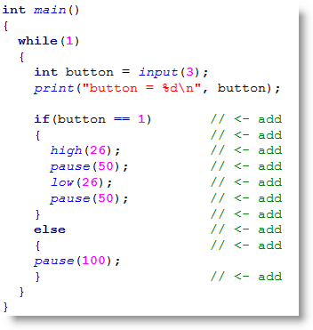
Remember if...else if... statements from Make Several Decisions? You can add one of those statements to your program to make the light blink if the button is pressed, or stay off and just wait for 1/10 of a second before repeating if the button is not pressed.
- Click Save Project As button, and save a copy of your project named Blink Light with Button.
- Modify the main function as shown below.
- Run the program and verify that the light blinks if you press and hold the pushbutton connected to P3.
Your Turn
Can you modify your program to make the LED connected to P27 blink when the button connected to P4 is pressed?
- Repeat the activities in this lesson using the P4 pushbutton and P27 LED.
- Combine them into a single program that uses the results of the P3 button to blink the P26 light and the P4 button to blink the P27 light.