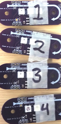
Before you proceed, use your masking tape and marker to label each board "1", "2", "3" and "4" to correspond with the ELEV-8 v3 boom that each PCB will eventually be installed on:
Next, you will be soldering the LED's on the front edge of the PCBs. Look carefully at the two pictures below. The WS2812B LEDs have a triangular notch that marks pin 1.

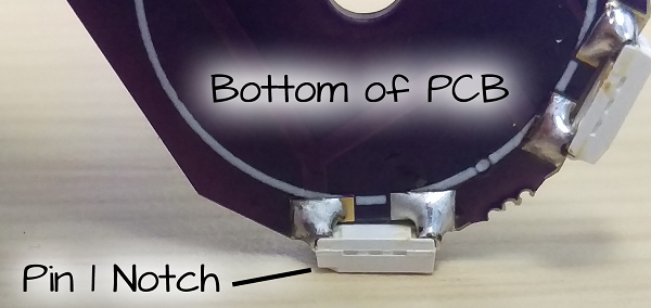
If you install the LEDs backwards, they (and any LED in the chain after one that is backwards) will fail, and potentially be damaged
To attach the LEDs to the front edge of the PCB:
- Set an LED upside down with the notch facing away from you.
- Hold the PCB vertically with the front facing toward you, and align the notch in the PCB over the LED.
- Use your soldering iron to "tack" one of the LED's pins to the PCB.
- Repeat for the second LED.
- Check to make sure the notch is in the right place on each LED by comparing it to the photographs above.
- If the LEDs are oriented correctly and aligned well, use your soldering iron to solder all 4 connections on the top of the PCB.
- Flip the PCB over and solder the remaining 4 connections for the LEDs.
Next you will be installing the headers.
- Use a pliers to break the 40-pin header into twelve 3-pin headers (you will have a few pins left over).
- Set the PCB on top of two 3-pin headers.
- Solder one of the header pins on each side.
- Check to make sure they are aligned well.
- Solder the remaining pins on the two 3-pin headers.
Finally, you will be solder-bridging the jumpers on the PCB.
Follow these instructions carefully. Configuring these jumpers incorrectly could destroy the LED modules and your ELEV-8 v3 Flight Controller!
Your boards must be labeled 1, 2, 3 and 4 before proceeding.
- On PCB 1, solder over to close the jumper labeled "Close on 1, 2, & 3" ONLY.

- On PCB 2, solder over to close both jumpers.

- On PCB 3, solder over to close both jumpers.
- On PCB 4, solder over to close the jumper labeled "Close on 2, 3, & 4" ONLY.
