Build LED Circuits
You have blinked the built-in LEDs on your board. Now it’s time to build your own LED circuits on your cyber:bot board’s prototyping area.
Introducing the LED
A diode is an electrical part that only lets electricity flow through it in one direction. A light-emitting diode (LED) emits light when current passes through it. You have to make sure to connect an LED the right way for it to light up. If you plug an LED in backwards it will not hurt it, but it will not emit light.
An LED has two terminals: the anode and the cathode. In the picture below, the anode lead is labeled with the plus-sign (+), and it is the wide part of the triangle in the schematic symbol. The cathode lead is labeled with a minus-sign (-), and it is the line across the point of the triangle in the schematic symbol.
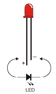
You can tell the anode and cathode apart by the shape of the LED’s plastic case. Look closely — it’s mostly round, but there is a small flat area near the cathode lead. Also note that the LED’s leads are different lengths. Usually, the shorter lead is connected to the cathode.
Always check the LED’s plastic case. Sometimes the leads have been clipped to the same length, or a manufacturer does not follow this convention.
Example LED Circuits
Let’s build two LED circuits on your breadboard. In addition to the two LEDs, you will need two resistors. Unlike the LEDs, the resistors do not have positive and negative leads, so you don’t have to worry about plugging them in backward. Resistors resist the flow of electrical current. Each one has a value that tells how strongly it resists current flow, measured in ohms, often noted by Greek letter omega: Ω. Take a look at that Resistor Color Codes page to see how its bands indicate its value.
Parts Needed
(2) red LEDs
(2) 220 ohm resistors (red-red-brown)
(misc) Jumper wires
- Put the cyber:board power swtich in position 0.
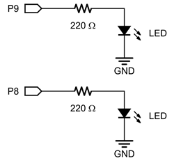
- Build two LED circuits, one each connected to P9 and P8, according to the schematic.
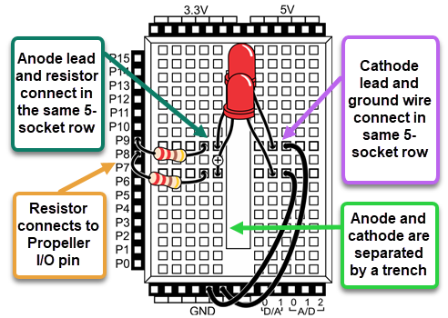
- Use the wiring diagram for your board, below, to double-check your work.
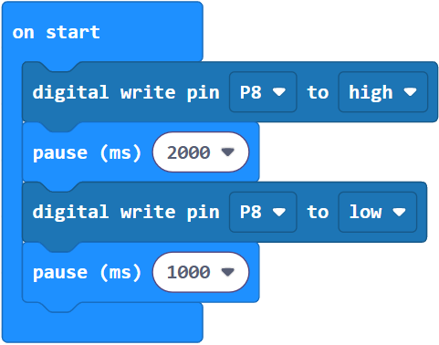
LED Test Project: pin_8_blink
This is the same test code that was used to blink the built-in P20 LED earlier in this tutorial, with the I/O pin number updated.
Enter and flash the project pin_8_blink.
- Move the power switch to Position 1, to power the breadboard circuits. The LED connected to P8 should start blinking.
- If it is not, check your wiring and try again. You might have the LED in backwards, or one of the leads or wires in the wrong socket.
- Once you have the P8 LED blinking, change Pin8 to Pin9, then re-run the code to test your P9 LED circuit.
- If you’ve verified that both your LED circuits are working, great! Continue on!
Your Turn
- Try changing the pause times for different effects.
- Try adding a pause call after the for loop.
- Try duplicating the for loop, and pasting it after that pause call. Then reverse its range from 9 to 7.
- Try modifying the program to make both of the LEDs blink at the same time.