Check Pushbuttons
Many items you use every day have pushbuttons. Cell phones, microwave ovens, TV remotes, and computer keyboards might all have pushbuttons. Can you think of others?
Let’s use a common pushbutton circuit and build a program for monitoring it with your microcontroller. Then, let’s use a pushbutton’s state to control LED circuits. LEDs are just one example of a device you can turn on and off with a microcontroller. Your invention might instead use pushbuttons to control circuits for motors, heating elements, or other devices.
The micro:bit module has two built-in pushbuttons. You can also add more pushbuttons to your cyber:bot on the breadboard. Doing so, you will learn how a pushbutton circuit works.
About Pushbuttons
A pushbutton is a device that makes an electrical connection between two of its terminal leads when its button is pressed. When the button is released into its normally-open state, the electrical connection is broken and no current flows through the device. Here is the schematic symbol:
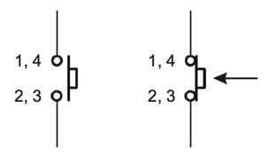
…and here is a drawing that resembles a breadboard-friendly pushbutton:
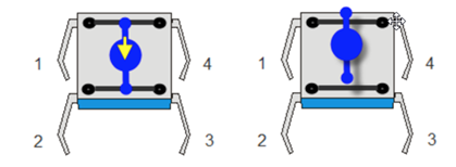
Notice that when the button is pushed, all 4 pins are connected. However, when the button is not pushed, legs 1 and 4 are still connected and legs 2 and 3 are still connected.
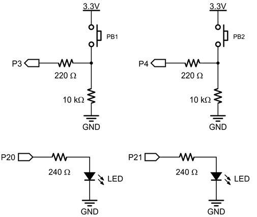
If the pushbutton is pressed, the circuit applies 3.3 V to the I/O pin through the pushbutton, and a small amount of current also passes through the 10 kΩ resistor to ground. When the pushbutton is not pressed, the connection to the 3.3 V supply is broken, and so the circuit applies GND (0 V) to the I/O pin.
Pushbutton and LED Circuits
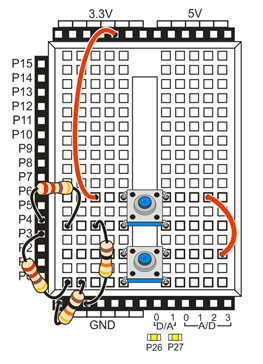
This circuit uses your board’s built-in P20 and P21 LEDs, along with two pushbutton circuits you will build onto your breadboard. Use 220 ohm resistors to connect the pushbutton circuits to the cyber:bot I/O pins and use 10 k-ohm resistors to connect the circuits to ground.
Parts
(2) pushbuttons
(2) 220 ohm resistors (red-red-brown)
(2) 10 k-ohm resistors (brown-black-orange)
- Build the two pushbutton circuits shown in the schematic and wiring diagram. We are also using the built-in LEDs on P20 and P21.
Test project: test_pin_3_button
This test project will display the state of the button connected to P3 on the micro:bit module’s display. The display will show a 1 if the button is pressed, or 0 if it is not pressed.
- Enter and flash the project test_pin_3_button.
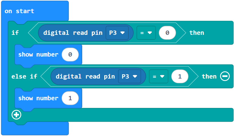
How test_pin_3_button Works
This Block code is all inside of a continuous forever loop. Inside the loop there is one if statement that checks two conditions.
The first condition that it checks is whether the (Pin3) read digital block is equal to 0. If this is true the micro:bit module will display a 0. The read digital block checks the input state of the pin, in this case P3. Thus, if the button is not being pressed, the input state at pin 3 is 0.
The second part of the if statement checks to see if the input state is 1 (button pushed), if so the micro:bit module will display a 1.
Did You Know?
Active-high: The pushbutton circuit you are using is called active-high because the pushbutton sends the cyber:bot I/O pin a 3.3 V high signal when pressed (active) or a 0 V low signal when released.
Pull-down: The 10 k-ohm resistor in the schematic is called a pull-down resistor. It’s there so that the I/O pin will detect 3.3 V through the resistor when the button is pressed. If you leave it out, the I/O pin behaves more like an antenna, and nearby electric fields will end up controlling whether 1 or 0 is detected.
Active-low, pull-up: Pushbutton circuits can also be active-low. All you have to do is swap the pushbutton and 10 k-ohm resistor in the schematic. The pull-down resistor then becomes a pull-up resistor, and the I/O pin will detect 0 V when the button is pressed.
Try This: pin_3_button_LED
Now it is time to control an LED with a pushbutton.
- Change the show number blocks to the write digital block to turn on the yellow LEDs attached to pin 20 when the button is being pressed.
- Change test_pin_3_button to pin_3_button_LED or make a new one
- Change display show (0) to (Pin20) write digital (Low) and change display show (1) to (Pin20) write digital (High).
- Enter and flash the project below:
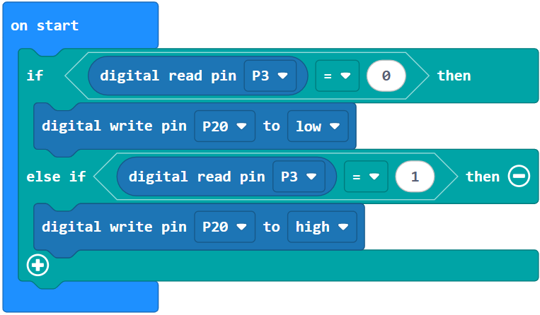
- Verify that the P20 LED blinks if you press the pushbutton connected to P3, and turns off when you release it.
Your Turn – P21 LED and P4 Pushbutton
Can you make the LED connected to P21 light when the button connected to P4 is pressed?
- Modify your Try This project to test controlling the P21 LED with the P4 pushbutton.
- Expand the code so that the P3 button controls the P20 LED and the P4 button controls the P21 LED at the same time.