Skip to content
Parallax Learn

Parallax Learn

  • Welcome
  • Tutorials
        • Tutorial Series head tag

          Tutorial Series
        • Tutorial Series

          The special, classroom-ready series pages are organized collections of tutorials for our most popular hardware and/or languages. The tutorials for each topic are conveniently accessible from a single page, shown in the order it is recommended that they be completed.
        • Robotics Series Head tag

          Robotics Series
        • Robotics Series

          • Artificial Intelligence
          • Cybersecurity: Radio Data tutorialCybersecurity
          • cyber:bot + Python
          • cyber:bot + MakeCode
          • Boe-Bot Tutorial SeriesBoe-Bot
          • Arduino Shield-Bot
          • ActivityBot with C TutorialsActivityBot + C
          • ActivityBot with BlocklyProp Tutorial SeriesActivityBot + BlocklyProp
          • Scribbler 3 Tutorial SeriesScribbler 3
        • Electronics & Programming Series Head tag

          Electronics & Programming Series
          • BS2 Board of Education Tutorial SeriesBS2 Board of Education
          • Propeller C-Language BasicsPropeller C Basics
          • FLiP Try-It Kit C Tutorial SeriesFLiP Try-It Kit + C
          • FLiP Try-It Kit BlocklyProp TutorialsFLiP Try-It Kit + BlocklyProp
          • Badge WX Tutorial SeriesBadge WX
          • Propeller BlocklyProp Basics and ProjectsPropeller BlocklyProp Basics
          • View All Tutorial Series »
        • Browse Tutorials
        • Browse Tutorials

          Individual tutorials sorted by robot or kit, and language.
        • By Robot or Kit
          • ActivityBot
          • SumoBot WX
          • Boe-Bot
          • Shield-Bot
          • cyber:bot
          • Badge WX
          • ELEV-8
          • ARLO
        • By Language
        • By Language

          • Propeller C
          • Arduino
          • BlocklyProp
          • PBASIC
          • Python
          • MakeCode
          • View All Tutorials »
  • Educators
  • Reference
  • Downloads
  • Home
  • All Courses

ELEV-8 v3 Quadcopter Assembly Guide

Curriculum

  • 1 Section
  • 40 Lessons
  • Lifetime
Expand all sectionsCollapse all sections
  • ELEV-8 v3 Quadcopter Assembly Guide
    40
    • 1.0
      Step 1: Do I Need to Loctite® the Set Screws?
    • 1.1
      Step 2: Attach Motors to Motor Mounts
    • 1.2
      Step 3: Feed Motor Wires Through Booms
    • 1.3
      Step 4: Bolt Motor Mount and Landing Gear to Booms
    • 1.4
      Step 5: Insert Tube Plugs
    • 1.5
      Step 6: Prepare the Top Chassis Plate
    • 1.6
      Step 7: Connect Booms to Top Chassis Plate
    • 1.7
      Step 8: Attach the Bottom Chassis Plate
    • 1.8
      Step 9: Attach Battery Straps and Foam Pads
    • 1.9
      Step 10: Connect the ESCs to the Motors
    • 1.10
      Step 11: Label ESC Signal Cables
    • 1.11
      Step 12: Route ESC Signal Cables through Chassis
    • 1.12
      Step 13: Bolt Standoffs to Isolation Plate
    • 1.13
      Step 14: Mount the Flight Controller and PDB
    • 1.14
      Step 15: Install the FC Power Cable
    • 1.15
      Step 16: Shield Sensors and Install FC Cover
    • 1.16
      Step 17: Attach the Isolation Assembly
    • 1.17
      Step 18: Connect the ESCs to the PDB and FC
    • 1.18
      Step 19: Connect and Mount Your Radio Receiver
    • 1.19
      Step 20: Connect PDB Power Cable and Secure Battery
    • 1.20
      Step 21: Configure the Transmitter and Bind to Receiver
    • 1.21
      Step 22: Install Software
    • 1.22
      Step 23: Install or Update Firmware
    • 1.23
      Step 24: Configure Flight Controller
    • 1.24
      Step 25: Calibrate the ESC Throttle Range
    • 1.25
      Step 26: Configure Motor Spin Direction
    • 1.26
      Step 27: Mount ESCs to Booms
    • 1.27
      Step 28: Full Systems Check
    • 1.28
      Step 29: Fasten Propeller Adapters
    • 1.29
      Step 30: Attach Propellers
    • 1.30
      Section 1: Assemble the Booms
    • 1.31
      Section 2: Assemble the Chassis
    • 1.32
      Section 3: Connect the ESCs
    • 1.33
      Section 4: Make the Isolation Assembly
    • 1.34
      Section 5: Install the Electronics
    • 1.35
      Section 6: Software and Firmware
    • 1.36
      Section 7: Configure the ESCs
    • 1.37
      Section 8: Final Testing
    • 1.38
      Step 19b: Spektrum AR610 and AR8000 Receivers
    • 1.39
      Step 19a: Spektrum SPMAR620 Receiver

Step 24: Configure Flight Controller

With the latest firmware now loaded onto your ELEV-8 Flight Controller, you will optimize it for your particular RC radio transmitter.

Parts Needed:

  • ELEV-8 v3 Assembly w/ LiPo Battery
  • Computer with software & firmware installed from Step 22
  • Fully Charged RC Radio Transmitter (not included)
  • USB A to Micro B cable (not included)

Instructions:

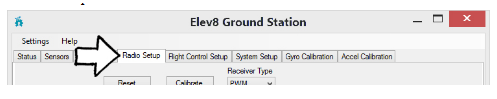
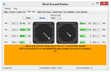
  1. Click on the Radio Setup tab.

Before proceeding, make sure that you have carefully followed the instructions in Step 21 for configuring your radio, or by carefully following the manufacturers instructions for setting up your transmitter.

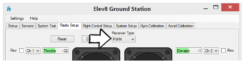
  1. Select your receiver type from the drop-down menu.  Most receivers are PWM, but be sure to double-check your transmitter’s specifications:

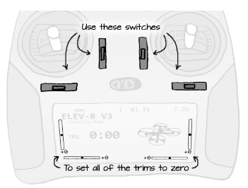
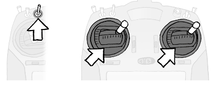
  1. Make sure that your Transmitter is on (and, if applicable, set to the model configured in Step 21), and that alll the trims are set to “zero” or “center”.

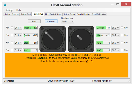
  1. Next, click the “Reset” button.  Move the right and left sticks around on your transmitter to verify their signals are being received by the flight controller.  When you move the sticks, the sticks on the screen should move too.  They may move in the opposite direction and they may not have the same range, but that is okay for now.
  2. Next, check the switches and knobs on your radio.  Flip each switch back and forth while watching the green bars on the GroundStation window.  Identify which switch is connected to the “Gear” (fifth) channel.  You may also be able to identify if any switches or knobs are connected to the “Aux 1”, “Aux 2”, or “Aux 3” channels, but these are optional and not required for flight.
  3. Once you have identified which switch is connected to the Gear channel, you can proceed with the calibration. Click the button labeled “Calibrate”.  The bottom of the screen will turn orange and contain instructions and a countdown timer.

During calibration, only actuate switches for the axullary channels. Do not move Dual-Rate (D/R) switches (leave them in high or disable them), or Throttle Arm/Disarm switches (leave in “Arm” postion). This is especially important for the Spektrum DXe Transmitter.

  1. On your transmitter, flip the Gear switch up (and if desired, any Aux switches or knobs) and push both sticks up and to the right.  Hold them there until the timer runs out and the GroundStation gives you the next instruction.

  1. The next instruction on the screen will ask you to move the sticks and switches in the opposite direction.

  1. Flip the Gear switch down (and if desired, any Aux switches or knobs) and push both sticks down and to the left.  Hold them there until the timer runs out and the yellow bar at the bottom of the screen disappears.

  1. Once the calibration process is complete, move both sticks and the Gear switch to verify that the sticks and switches now show the full range of motion.  If they do not, it may be for one or more of the following reasons:
  • Not holding the sticks correctly during the calibration process
  • A switch that was NOT identified as a Gear or Aux switch was flipped during calibration
  • Loose or disconnected cable between the receiver and flight controller
  1. If your sticks and switches are not showing the full range of motion after you have followed the calibration steps, try to identify and correct the error and repeat the calibration process. You can reassign and reverse the channels by using the checkboxes and drop-down menus for each channel.  This will allow you to fly your ELEV-8 v3 according to your preferences.
  2. When you have finished setting up your Transmitter and everything appears to be functioning correctly, click the “Upload Changes” button on the bottom of the screen.

Printer-friendly version
Step 23: Install or Update Firmware
Prev
Step 25: Calibrate the ESC Throttle Range
Next

DISCUSSION FORUMS | PARALLAX INC. STORE

About | Terms of Use | Feedback: learn@parallax.com | Copyright©Parallax Inc. 2024

© 2026 Parallax Learn • Built with GeneratePress