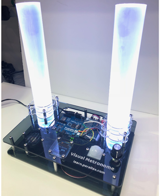
Metronome Assembly and Code Overview
The key physical design element of the Visual Metronome is the NeoPixel light transmission through two 1-½” diameter, 10-inch long clear acrylic rods. This is the same diameter as the NeoPixel rings; when they’re placed right against the end of the acrylic rod the light transmits directly to the other end. By sanding the sides, the light comes through the entire length of the rod. These acrylic rods can be found on eBay or Amazon, or from plastic acrylic suppliers.
The base of the Visual Metronome was laser-cut from ⅛” smoked acrylic pieces. The acrylic base in this example was assembled with #4-40 screws and standoffs. The base can be made from nearly anything: wood, foam core board, cardboard, or Sintra. Depending on your design, hot glue or screws might be the appropriate fastener!
If you’d like to build the Visual Metronome using our design, the files are available as a DXF which you may freely use. The two main base plate parts are ⅛” thick transparent smoked acrylic and the holders for the 1-½” acrylic rods are ⅛” thick clear acrylic. Standoffs are 1” aluminum round 4-40s. An assortment of 4-40 screws of ⅜” to ½” long are also helpful. Download DXFs from the download page here on Learn.
Electronics Block Diagram
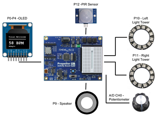
The wiring diagram works like this:
-
P0 through P4 to the OLED
-
P9 to the speaker
-
P10 and P11 to the two NeoPixel rings
-
P12 to the PIR Sensor
-
A/D CH0 to 10K Ohm potentiometer
Each component also has power and ground connections.
A Parallax 7.5V 1.5A Power Supply (#750-00009) is plugged into the power jack. The P12 and P12 servo header jumpers are set at 5.0V.
BlocklyProp Code Overview
- Start a program with Board Type “Other”.
BlocklyProp is designed so that different board types have only relevant block types available to them. The use of the system counter and wait until blocks are available in the “other” board type. However, the analog voltage block is only available for the Propeller Activity Board WX board type.
The solution to this problem is to start building your program with the “other” board type and then move that program into a new project with the “Propeller Activity Board WX” board type.
- Once you’ve placed all the system blocks on the “other” board type workspace, choose “Download Blocks File”. Save it somewhere on your computer.
- Next, start a new program with the “Propeller Activity Board WX” as the board type.
- Import the files from the “other” board type into this new workspace using the “Upload Blocks File” option.
Code Explanation
Coding an accurate metronome on a microcontroller presents a few timing challenges. For example, writing data to an OLED, illuminating the NeoPixels, and control structure statements require unknown amounts of time to execute. Adding pauses and delays doesn’t make it much easier, and the use of external real-time clock represents additional code overhead, too.
The Propeller Multicore Microcontroller has two key hardware features for making a metronome with deterministic timing. The first is the use of an accurate system clock with an elapsed time counter, both readily available to the BlocklyProp programmer. The system counter block provides a current value of clock ticksand the Wait until block stops the program until an elapsed time has passed. The two blocks look like this:


The second feature is the Propeller’s eight parallel processors with shared memory, allowing the time-consuming code overhead of the OLED to run in its own processor in the main loop while the system counter process runs in its own processor.
The entire code for this project can be downloaded from the link below:
Project53482-Visual-Metronome.svg
At first look the code appears to use two processors – the Main Loop and metronomeTime. However, the OLED, RGB LEDs and A/D also run in their own processors. Some BlocklyProp commands do this in their libraries without the new processor block (a reference of those blocks which use their own processors is available on Learn). This brings the total usage in the Visual Metronome to five processors.
The Visual Metronome psuedocode could be summarized as follows:
-
The main processor:
-
Starts another new processor with the function “metronomeTime”
-
Checks the PIR Sensor for motion and increments a counter
-
Determines the tempo (BPM) from the potentiometer reading (the A/D converter starts another processor)
-
Writes the Italian tempo marking as a string into a variable
-
Writes the tempo to the OLED (the OLED starts another processor)
-
-
The metronomeTime processor:
-
Calls a function which checks the potentiometer analog value
-
Creates the msTicks variable from the system clock frequency
-
Runs a loop counter which waits for an elapsed time to pass
-
Sets NeoPixel colors (the RGB blocks start another processor)
-
Sounds a speaker or creates a delay
-