This C-language tutorial for the 8-core Propeller microcontroller. It features the Propeller Activity Board (original or WX version). Other Propeller boards will work in most cases; check each activity’s circuit for notes.
This set “a-la-carte” collection of lessons shows you how to interface a variety of devices to the multicore Propeller microcontroller. Each page includes a schematic, wiring diagram and test code with C libraries that make the programming simple. You do not need to do these in order, just pick what interests you. We will let you know if two lessons are meant to work together.
Keep checking back, because we will keep adding more.
You will be ready to design your own projects that combine these devices.
The PING))) Ultrasonic Distance Sensor measures the round-trip echo time of ultrasonic sound to determine how far away an object is. It can measure distances anywhere from 3 centimeters to 3 meters. In addition to being a great distance sensor for robots, it’s also useful for detecting people passing through doorways, viewing art exhibits, approaching holiday props, and lots more.
Want to go a bit more in-depth? Then be sure to check out this reference article about the speed of sound vs. air temperature, and learn how the temperature can actually affect distance measurements from your PING))) sensor.
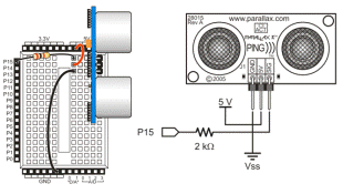
The PING))) Ultrasonic Distance Sensor only needs three connections to do its job: I/O pin, 5 V, and GND.
(1) PING))) Ultrasonic Distance Sensor (#28015)
(1) 2 k-ohm resistor (red-black-red, #150-02020)


Different Board? if you are using a different Propeller board, build the equivalent circuit using the schematic.
Servo Ports? Another option is to set the Activity Board’s P15 servo port power jumper to 5V, and then connect the PING))) sensor to the port with a 3-pin F/F extension cable. There is a 3.9 k-ohm resistor in series between the signal pin in each servo port and its Propeller I/O pin, so no additional resistor would be needed.
The test code displays the distance in centimeters to an object placed in front of the sensor.

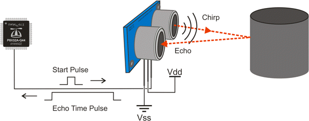
After the PING))) sensor receives a low-high-low Start pulse from the Propeller, it makes a brief ultrasonic chirping sound. Since it’s ultrasonic, humans cannot hear it, but it’s loud enough that its own ultrasonic transducer can detect when the echo comes back.
As soon as the PING))) sensor makes its chirp, it sets its output pin high. When the echo comes back, it sets the pin low. The Propeller measures how long the PING))) sensor holds this pin high, and that number is the round trip time for the sound to return.
The ping library has functions that take care of sending the start pulse and measuring the echo time pulse. It also has functions that use the speed of sound in air to convert the echo time to a centimeter distance.
The ping library was added to this project by clicking the Add Simple Library button, and navigating to …Documents\SimpleIDE\Learn\Simple Libraries\Sensor. Then, select the libping folder, and click the Select Folder button. After adding it to your project you’ll have access to all of the the ping library’s functions.
In this program’s while(1) loop, int cmDist = ping_cm(15) makes a PING))) sensor connected to P15 report echo time. It stores that time as a microsecond measurement and then uses the speed of sound in air to convert to a centimeter measurement. int cmDist = ping_cm(15) copies the centimeter result the ping_cm function returns to a variable named cmDist. After that, print(“cmDist = %d\n”, cmDist) displays this value along with a newline character so that the next measurement appears on the next line in the SimpleIDE terminal. After a 1/5 second delay made possible by pause(200), the loop repeats to display the next distance measurement.
/*
  Test Ping Distance.c

  Measure and display Ping))) Ultrasonic Distance Sensor distance measurements.
*/

#include "simpletools.h"                      // Include simpletools header
#include "ping.h"                             // Include ping header

int main()                                    // Main function
{
  while(1)                                    // Repeat indefinitely
  {
    int cmDist = ping_cm(15);                 // Get cm distance from Ping)))
    print("cmDist = %d\n", cmDist);           // Display distance
    pause(200);                               // Wait 1/5 second
  }
}
The speed of sound in air is 344.8 meters per second at room temperature (about 72 °F or 22.2 °C). That’s c = 344.8 m/s, T = 72 ºF or 22.2 ºC.
The distance (s) sound travels over a certain time is the product of the speed of sound and time. That’s s = c × t. If you are solving for round trip, the sound has to go twice as far, which takes twice as long, so divide your result by 2. That’s s = c × t ÷ 2. There are 100 centimeters in 1 meter, and 1,000,000 microseconds in 1 second. That’s 1 m = 100 cm and 1 s = 1,000,000 µs.
So, if you have an echo time in microseconds and you want a distance measurement in centimeters it’s:

0.01724 happens to be really close to 1/58. The ping library uses s = t ÷ 58 because integer math saves memory and gets that job done more quickly than floating point.
Here is an example that uses the centimeter distance measurement to control the brightness of the LED connected to P27. (You can use an LED on any available Propeller I/O pin. For a refresher on how brightness control works, see Set Volts.)
This particular example has a 25 cm range. The closer the object gets, the dimmer the light gets.

This program restricts the measurement to a maximum of 25 with if(cmDist > 25) cmDist = 25. Then, cmDist is multiplied by 10, since the dac_ctr function expects a value from 0 to 255. Finally, dac_ctr(27, 1, cmDist) takes the scaled-up cmDist value to control the LED with a range from 0 to 250 — almost the full range of LED brightness. cmDist is re-initialized with the sensor measurement ping_cm(15) each time the loop repeats.
SD cards can give your Propeller microcontroller invention some extra gigabytes of memory to work with. In this lesson, we’ll look at simple data storage and retrieval. Later, we’ll look at audio and music applications and even writing code that can run from an SD card.
(1) 2 GB microSD card (#32319)
This lesson was written for the Propeller Activity Board (original or WX version). It will also work with the Propeller Board of Education. If using a different Propeller development board, connect the card reader to the Propeller I/O pins listed below in How it Works, or update the global int variables at the beginning of SD Minimal.side to match your circuit.
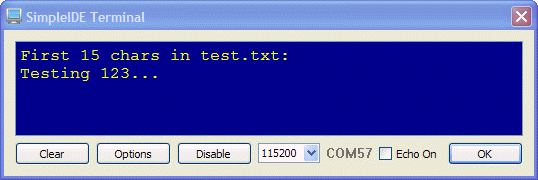
The SD Minimal.side project creates/opens a file on the SD card named test.txt for writing. It then writes a string of characters into the file and closes it. It then reopens it for reading, copies the contents to a character array, which gets displayed in the SimpleIDE Terminal.
If the SimpleIDE Terminal just displays a blank screen, try SD with Tests. It uses a more common procedure of checking for errors at each step in the file system mounting and file opening steps, and will display messages about certain problems encountered while executing the program.
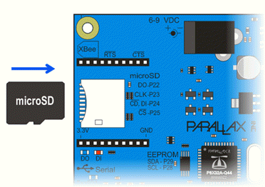
See the metal stripes under the SD card? Those are the electrical connections, called pads, that a device uses to communicate with the memory chip inside the card.
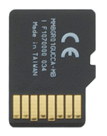
DO, CLK, DI, and CS are names for certain pads in the SD card. Those pads get connected to Propeller I/O pins when you plug an SD card into a Propeller Activity Board (original or WX version) socket. The Propeller chip will send control signals to CLK, CS, and data to DI. It will also receive data from DO.
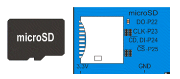
First, four global variables are named and initialized for the microSD card pads, and the Propeller I/O pins they will be connected to through the board’s card socket: int DO = 22, CLK = 23, DI = 24, CS = 25;
These global variables are used by name in the function call sd_mount(DO, CLK, DI, CS). This gives the SD driver library the information it needs to open the SD card and get its file system information.
Once sd_mount opens the file system, you can then use functions from the stdio library (included by simpletools.h) to create and use files on the SD card. The first such function call is FILE* fp = fopen(“test.txt”, “w”).
The fopen function creates a file (if it doesn’t already exist) and returns a value called a file pointer, here named fp. fp will initially point to the start of the file. Later on, fp is used in operations for opening, writing to, reading from, and closing the file.
The fopen function takes two parameters. First is a character array with the file name “test.txt” in our example. Second is the mode, “w” in our example, which means the opened file can be written to. (Other options include “r” for read and “a” for append.)
Characters can be written to the file with the fwrite function. In our example, fwrite(“Testing 123…\n”, 1, 15, fp) copies the characters in the string to successive locations in the test.text file. The fwrite function takes a pointer to a buffer of data (our string “Testing…”), the size of each element of data in bytes (1), the number of data elements to write (15 bytes; characters), and a pointer to the file (fp) to write to.
When done, fclose(fp) closes the file.
Next, the program sets up a character array with char s[15]; as a buffer to store data read from the SD card file. Then, the file is opened for reading with fp = fopen(“test.txt”, “r”). Then, fread(s, 1, 15, fp) tells the file system to copy data to the s character array, in 1 byte chunks, a total of 15 bytes, starting at the fp file pointer. Since the file was just opened, fp points to the beginning of the file. When done, fclose(fp) closes the file again.
Finally, print(“%s”, s) displays the values that fread placed in the s character array. The %s format placeholder tells the print function to send the values in the character array as a string of ASCII characters to the SimpleIDE Terminal. One last print(“\n”) moves the cursor down one line in the terminal.
/*
  SD Minimal.side

  Create test.txt, write characters in, read back out, display.
*/

#include "simpletools.h"                      // Include simpletools header

int DO = 22, CLK = 23, DI = 24, CS = 25;      // SD card pins on Propeller BOE

int main(void)                                // main function
{
  sd_mount(DO, CLK, DI, CS);                  // Mount SD card

  FILE* fp = fopen("test.txt", "w");          // Open a file for writing
  fwrite("Testing 123...\n", 1, 15, fp);      // Add contents to the file
  fclose(fp);                                 // Close the file

  char s[15];                                 // Buffer for characters
  fp = fopen("test.txt", "r");                // Reopen file for reading
  fread(s, 1, 15, fp);                        // Read 15 characters
  fclose(fp);                                 // Close the file

  print("First 15 chars in test.txt:\n");     // Display heading
  print("%s", s);                             // Display characters
  print("\n");                                // With a newline at the end
}
Look around the SD Card examples folder—there is an example that allows you to test if the SD card is responding before attempting to read or write data.
stdio library — The functions fread, fwrite, fopen, and fclose are part of the stdio.h library, which is included with the Propeller GCC compiler. Check here for a complete list of stdio file input/ouput functions: http://en.wikipedia.org/wiki/C_file_input/output.
fprintf and fscanf – There are some other functions available to edit files, in much the same way as fwrite and fread, called fprintf and fscanf. These functions, however, use far more memory than fwrite and fread, so they are not used here. Feel free to investigate for yourself!
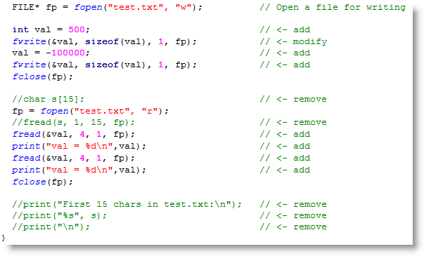
Just as you can use print(“%d\n”, val) to display a value, so you also can use fwrite(&val, sizeof(val), 1, fp) to store a value on the SD card. Then, it is possible to retrieve the value with the function fread. Let’s try it.
Good sensor choices include:
This type of project is called sensor datalogging, and has numerous applications in industry and the sciences.
Playing WAV files can enhance your project with music, a variety of tones, voice recordings, or even sound effects. The multicore Propeller chip is particularly well suited to playing WAV files because it can use a couple of its cores for reading the SD card and D/A conversion, while other cores can adjust the playback volume, change files, or even execute code for sensors or displays.
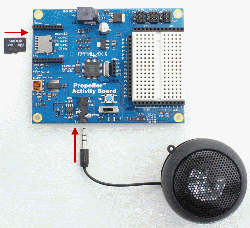
The Propeller Activity Board (original or WX version) has built-in audio D/A amplifiers and a microSD card holder. The Propeller microcontroller can fetch the audio data off the card, and use the D/A amplifiers to play back the sounds.
(1) FAT32 formatted microSD card (we used the preformatted microSD Parallax #32319; other SD cards might not provide the same sound quality)
(1) speaker or headphones with 3.5 mm plug (we used the Veho speaker, Parallax #900-00018)
This lesson was written for the Propeller Activity Board (original or WX version). It will also work with the Propeller Board of Education. If using a different Propeller development board, connect the card reader to the Propeller I/O pins listed below in How it Works, or update the int variables at the beginning of Test WAV Volume.c to match your circuit.
The wavplayer library is designed for 16-bit PCM, 32 kHz, mono WAV files. A good source of free WAV files is www.freesound.org. Audacity is an excellent audio editor for converting other files to this format.
Before running this program, Let’s download a sample WAV file and load it into the SD card. (Hint: to keep from simply playing the WAV file with your browser, right-click the link and choose Save Link As… or Download Linked File.)
Now, let’s test the playback. The Test WAV volume application plays at a volume of 6 (out of 10) for 3.5 seconds, then a volume of 4 for 2 more seconds, then a volume of 8 for 3.5 seconds, before stopping the playback.
Looking for pre-formatted, ready-to-use audio files? See our Sound Library
Want to create your own audio files? See Creating Audio Files for WAV Players
Need to reformat audio to WAV? See Formatting Audio Files for WAV Players
This project includes simpletools.h and wavplayer.h.
First, four int variables are named and initialized for the microSD card’s pads, and the Propeller I/O pins they connect to through the board’s card socket: int DO = 22, CLK = 23, DI = 24, CS = 25;
Then, a call to sd_ mount accesses the SD card’s file system, using these variables by name: sd_mount(DO, CLK, DI, CS);. (We could have just called sd_mount(22, 23, 24, 25), but named variables makes the code easier to understand and adapt if you are not using a Propeller Activity Board.)
After that, const char techloop[] = {“techloop.wav”} creates a character array with 12 slots, and fills them with the characters t e c h l o o p . w a v. This array gets passed to the wav player with wav_play(techloop).
When the WAV player receives that string of characters, it searches for a file with that name in SD card’s root directory. It then opens the file, reads the header information about data rate, bits per sample, and other details. Then, it launches two more Propeller cores, or cogs.
One cog fetches the D/A values from the WAV file and store them in an array. The second cog grabs values from that array, and uses them to set the D/A converter output.
That second cog updates its D/A output by reading the values in the array at a rate of 32,000 times per second, and updating the D/A converter’s output with each D/A value from the WAV file.
When the WAV file is playing, calls to wav_volume change the volume setting. This function’s vol parameter accepts integers in the range of 0 to 10.
Finally, a call to pause sets the play time for that particular volume. Note that each call to wav_play also needs a call to wav_volume (either before or after). Each call to wav_play also needs to be followed by a pause. The call to pause dictates how long the wav file will play. To hear an entire wav file, the call to pause must be about 900 ms longer than the length of the file.
/*
  Test WAV Volume.c

  Play back a .wav file and try a few different volume settings.
*/

#include "simpletools.h"
#include "wavplayer.h"

int main()                                        // main function
{
  int DO = 22, CLK = 23, DI = 24, CS = 25;        // SD I/O pins
  sd_mount(DO, CLK, DI, CS);                      // Mount SD card

  const char techloop[] = {"techloop.wav"};       // Set up techloop string
  wav_play(techloop);                             // Pass to wav player

  wav_volume(6);                                  // Adjust volume
  pause(3500);                                    // Play for 3.5 s
  wav_volume(4);                                  // Repeat twice more
  pause(2000);
  wav_volume(8);
  pause(3500);

  wav_stop();                                      // Stop playing
}
wavplayer library — This useful collection of functions also includes wav_playing to find out if the WAV file is still playing, and wav_stop to stop playback.
Switch tracks — You can call wav_play even if you are in the middle of playing back something else. The library will automatically stop what it’s playing and then start playing the next one.
More WAV files to play with — Our Sound Library is not a C library, but a small collection of ready-to-use WAV files, links to other sites with public domain sounds, and instructions for using Audacity to format audio files for use with Propeller projects.
Thank you, sonicspot.com — The WAV player was developed with information about WAV files from this very helpful page: http://www.sonicspot.com/guide/wavefiles.html
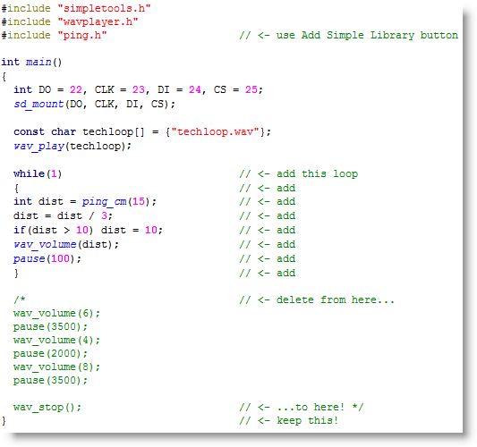
Since the WAV file is playing in other cogs, your code is free to work on other things, such as checking sensors. Here is an example where the volume is set by a measurement from a PING))) Ultrasonic Distance Sensor. We’ll add the ping library to our project by adding the #include “ping.h” directive to our code.
(Note: you must be using SimpleIDE 0.9.4 or later to have #include automatically add a library to your project, for earlier versions use the Add Simple Library button)
The Memsic MX2125 Dual-axis Accelerometer is great for measuring tilt, vibration, rotation, and let’s not forget its namesake, acceleration. A few MX2125 project ideas might include a tilt video game controller, tilt robot controller, robot hill climbing sensor, and radio vehicle acceleration, speed, and position data logger.
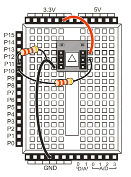
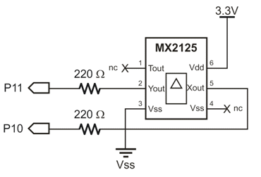
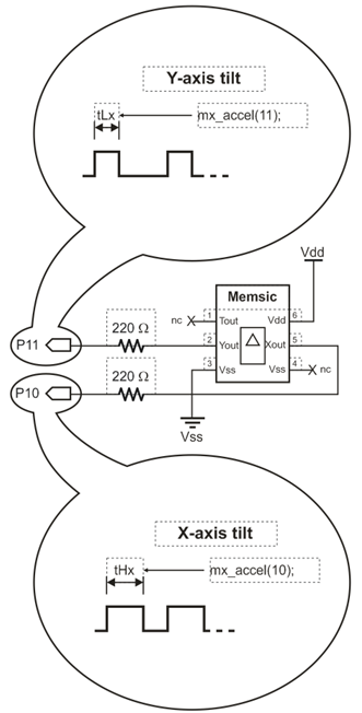
The MX2125 sends two acceleration signals, one for its x-axis, and a separate one for its y-axis. In this test, we’ll use P11 to monitor the y-axis signal and P10 to monitor the x-axis signal.
(1) Memsic2125 Accelerometer (#28017)
(2) 220 ohm resistors (red-red-brown, #150-02210)
This lesson will work on any Propeller development board with a prototyping area.
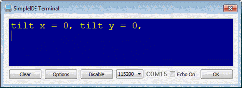
The Test 2125 Tilt application reports tilt in two directions: y-axis (left/right) and x-axis (toward/away from you).
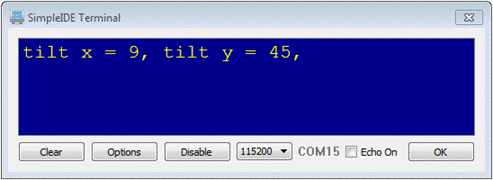
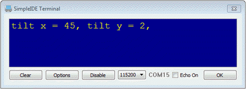
The MX2125 sends out two streams of pulses, one for the X axis and one for the Y axis. These high pulses last about 5000 µs (microseconds) when the board is held level.
As the board is tilted, the high pulses will vary across a range of 3175 to 6125 µs. Functions inside the mx2125 library scales these measurements to a range of +/- 1250. After that, it converts the measurements to degrees with a maximum range of +/- 90. (The output range of your particular MX2125 unit may vary.)
You can add the mx2125 library to any project with the Add Simple Library button. Just click it, navigate to …Documents\SimpleIDE\Learn\Simple Libraries\Sensor\libmx2125, and click OK. This incorporates all of the library’s files into your project and adds #include “mx2125.h” to your code.
This library puts functions named mx_accel, mx_tilt, and mx_rotate at your service.
Here, P10 is connected to the MX2125’s Xout pin, so int x = mx_tilt(10) gets the x-axis tilt measurement and stores it in a variable named x.
Similarly, int y = mx_tilt(11) gets the y-axis tilt and stores it in a variable named y.
In the example below, these measurements are taken and displayed with a print statement, every 200 ms in an endless loop.
/*
  Test 2125 Tilt.c

  Measure tilt.  Assumes MX2125 is being held horizontally and then tilted.
*/

#include "simpletools.h"                          // Include simpletools header
#include "mx2125.h"                               // Include mx2125 header

int main()                                        // Main function
{
  while(1)                                        // Repeat indefinitely
  {
    int x = mx_tilt(10);                          // X-axis tilt
    int y = mx_tilt(11);                          // Y-axis tilt
    print("%ctilt x = %d, tilt y = %d, %c\n",     // Display tilts
            HOME,       x,           y, CLREOL);
    pause(200);                                   // 1/5th second before repeat
  }
}
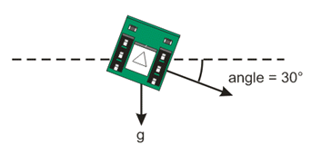
The MX2125 has a tiny chamber inside that’s filled with nitrogen gas. There’s a heating element in the middle, and temperature sensors around chamber’s sides.
As you tilt the MX2125, the hotter gas rises. The temperature sensor(s) closest to the hot gas detect these higher values. Circuits inside the sensor use those temperature measurements to control the duration of the high output pulses that a microcontroller can read.
How does this work for measuring acceleration? First, think about having a partially filled water bottle in a car seat. As the car accelerates, the heavier water sloshes away from the direction the car is accelerating, pushing the lighter air forward. The cooler nitrogen gas behaves like the water in your water bottle, sloshing away from the direction the sensor is accelerating. Also like the water bottle, it displaces the hotter nitrogen gas toward the direction of acceleration. The temperature sensors pick this changing temperature pattern, and update the output pulse widths accordingly.

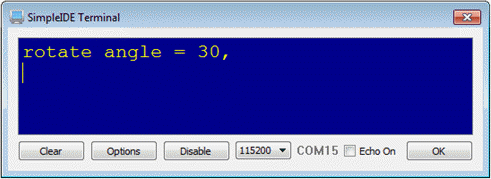
You can hold your board vertically in front of you and turn it like it is a steering wheel. The mx2125 library’s mx_rotate function will return the board’s rotation angle in degrees, 0 to 359.
Hint: for character position, you’ll need to use some math on the x and y values to scale them into a range 0 to 20. Then, use print(“%c%c%c*”, CRSRXY, x, y) to place an asterisk in the SimpleIDE Terminal, or print(“%c%c%c ”, CRSRXY, xOld, yOld) to blot out the previously positioned asterisk with a space.
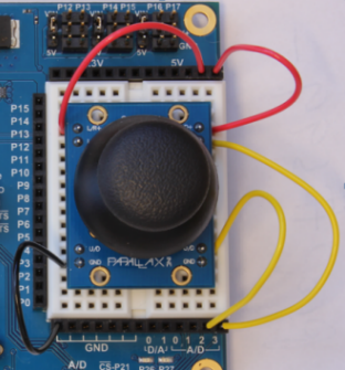
The Parallax 2-Axis Joystick can be used for a wide variety of projects like wheeled robots, video games, or anything requiring user input. Like most joysticks, the Parallax 2-Axis Joystick uses two variable resistors (called potentiometers) to read the user’s input. Remember reading a potentiometer’s value back in Measure Volts? Reading a joystick’s position is a matter of measuring two potentiometer voltages. One reports the left/right position and the other reports the up/down position.
?
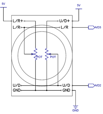
The Parallax joystick contains two 10 kΩ potentiometers, one for each axis. We’ll read the value from the potentiometer using an analog to digital converter, or ADC, just like in Measure Volts. For our joystick, we’ll use one of the ADC’s inputs for each axis. In this case, up/down (U/D) is connected to channel 2 and left/right (L/R) is connected to channel 3. The potentiometer also needs to be powered, so we’ll attach the potentiometer’s pins labeled L/R+ and U/D+ to 5 V, and the GND pin to ground. Note that there are two of some of these pins—it doesn’t matter which one you use, they are electrically the same.
(1) Parallax 2-Axis Joystick (#27800)
Note: This lesson is designed for the Propeller Activity Board (original or WX version). It is not compatible with the Propeller Board of Education, which uses a different A/D converter.
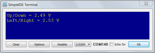
This test code will read both axes of the joystick and display voltage values for each. Since the potentiometer is connected to 5 V, the middle of the joystick (where it goes when you release it) will display 2.5 V on both axes. You may notice slight deviations from 2.5 V; this is explained more in the Did You Know? section.
The code includes the adcDCpropAB library with the command #include “adcDCpropAB.h”. This library is designed for measuring voltages using the A/D converter on the Propeller Activity Board (original or WX version). The function adc_init gets called first, to tell it which Propeller I/O pins are connected to the A/D converter’s /CS, SCL, DO and DI pins. Together these pins are called an SPI bus, over which the Propeller communicates with many peripheral devices. You will find the SPI pin numbers next to the A/D converter chip, which is right below the GND sockets on your board.
After that function, float x, y declares two floating point variables for storing measurements. Inside the while(1) loop, udV = adc_volts(2) stores the voltage at A/D2 into the udV variable, and lrV = adc_volts(3) does the same for A/D3. A couple of print calls display the two voltage values, followed by a 1/10 second pause before the loop repeats.
/*
  Joystick.c

  Simple demo with the Parallax 2-axis Joystick.
*/
#include "adcDCpropab.h"                            // Include adcDCpropAB
#include "simpletools.h"                            // Include simpletools


int main()                                          // Main function
{
  adc_init(21, 20, 19, 18);                         // CS=21, SCL=20, DO=19, DI=18

  float lrV, udV;                                   // Voltage variables

  while(1)                                          // Loop repeats indefinitely
  {
    udV = adc_volts(2);                             // Check A/D 2
    lrV = adc_volts(3);                             // Check A/D 3

    putChar(HOME);                                  // Cursor -> top-left "home"
    print("Up/Down = %.2f V %c\n", udV, CLREOL);    // Display voltage
    print("Left/Right = %.2f V %c\n", lrV, CLREOL); // Display voltage

    pause(100);                                     // Wait 1/10 s
  }
}
Instead of displaying the voltage values from the joystick, let’s display a range representing the joystick’s position. To do this, we’ll need to scale voltages going from 0 to 5 V into values from -100 to 100.
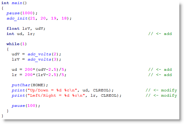
You may want to drive a servo with your joystick. Perhaps you want your servo to start at 90 degrees and move ±60 degrees from there. Write some code to do this scaling, and output the result for each axis on the terminal.
Hint: to display the “%” character in the serial terminal, we need to type two of them in the print command. This is because % acts as a special operator in print commands so it is necessary to have two % characters tell print to display a literal “%.”
A hobby servo is a small device that controls the position of flaps, rudders, and steering in many radio-controlled toy planes, boats, and cars. The Parallax Standard Servo is a hobby servo, and it’s also useful in many robotics and animatronics projects. Since it can both move to and hold a position, it is ideal for tasks like rotating a distance sensor or controlling the fingers in a robotic hand.
This tutorial will show you how to make a servo hold three different positions, and then guides you through creating smooth, continuous motion through small, evenly-timed changes in position.

(1) Parallax Standard Servo (#900-00005)
(1) 3” Jumper Wire (#800-00016)
(1) Power supply. Options include:
A servo can draw more current than a USB port can supply, so you’ll need to plug an external power supply into the Activity Board’s 6 to 9 V power jack. Since the Parallax Standard Servo is rated for a 4 to 6 V supply, you may also need to move the Activity Board’s servo port power jumper settings to regulated 5V.
There are three pins to the immediate left of each pair of servo ports on the Propeller Activity Board (original or WX version). A small metal and plastic jumper can connect the middle pin to either the top or the bottom power pin. This is the power-select jumper for that pair of servo ports. When the jumper is over the bottom and middle pins, the pair ports’ V+ pins receive 5 VDC through the board’s voltage regulator. When the jumper is over the middle and top pins, the ports’ V+ pins receive unregulated voltage directly from the power supply connected to the board.

It helps to make some sort of angle marker on the turning part of the servo (called its control horn) to know what position it is in. A jumper wire is handy for this.


If you haven’t already installed the latest USB driver, SimpleIDE, or Learn folder, go to Propeller C – Set up SimpleIDE and Propeller C – Start Simple.
The servo test code will move the servo to the three positions shown below (0°, 90°, and 180° ) with three seconds to move between and hold each position. While the program is running, the servo will resist any attempt to move it out of position. When the program finishes, the servo will stop resisting.
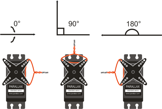
The servo_angle() function call takes two parameters: the pin the servo is connected to and the servo angle in tenths of a degree. For example, to make the servo connected to P16 turn to 90 degrees, the program uses servo_angle(16, 900). Keep in mind servo_angle() does not wait for the servo to get into position—it is necessary to include a pause for the servo to reach the desired position before setting a new angle.

/*
  Standard Servo Position.c

  Moves servo to 0, 90 and 180 degrees.  Holds each position for 3 s.
  Connect servo to P16 port on Propeller Activity Board.
*/

#include "simpletools.h"                      // Include simpletools header
#include "servo.h"                            // Include servo header

int main()                                    // main function
{
  servo_angle(16, 0);                         // P16 servo to 0 degrees
  pause(3000);                                // ...for 3 seconds
  servo_angle(16, 900);                       // P16 servo to 90 degrees
  pause(3000);                                // ...for 3 seconds
  servo_angle(16, 1800);                      // P16 servo to 180 degrees
  pause(3000);                                // ...for 3 seconds
  servo_stop();                               // Stop servo process
}


Satellite dish image source: https://commons.wikimedia.org/wiki/File:Goldstone_DSN_antenna.jpg
Servos aren’t just for hobbies. Much larger servos are used to precisely aim the position of huge satellite dishes towards extraterrestrial targets, like those in the Deep Space Network (above, left). Additionally, most robotic hands (like the one above that is preparing to make sign for number 7 in ASL, right, though it can’t quite reach since the palm is not articulated.) are actuated by servos. Depending on how many independent degrees of freedom the hand has, it could use dozens of servos! The hand above is actuated using five standard servos.
Let’s use a feature called ramping to make the servo move to new positions gradually. Ramping “cushions” or “smooths-out” the servo’s responses to large or sudden changes in sensor measurements by limiting how much it can change position over a given amount of time. This servo control library’s servo_setramp() function takes two parameters: the servo’s pin, and the speed at which the servo will change in tenths of a degree per 50th of a second.
Once servo_setramp() is called, every servo_angle() call that follows it will move at the rate set by servo_setramp. Without this command, the servo will always move to new positions at its maximum speed. In this example, the servo will move to its first two positions at full speed just like it did in the program above. Then servo_setramp(16, 8) will slow it down to .8° per 50th of a second as it moves to the last two positions.

In this example, the servo moved from 180 degrees back to 90 degrees more gradually because of servo_setramp(), but it still made it there and paused. What do you think would happen if you changed the rate to .5 degrees per 50th of a second? Would the servo make it to 180 degrees before turning back? Try it!
Imagine you’re the engineer in charge of animatronic devices at an amusement park. Let’s say one exhibit contains two servos for its face, and needs to display five expressions, one each thirty seconds. One way to do this would be by storing these expressions in two arrays (one for each servo).
If you haven’t worked with array variables before, check out the Array Variables tutorial. Then, try the Index Array Variables tutorial and pay close attention to how the code loops through an array using a for loop and then uses print() to display the values. Instead of displaying the values in the arrays with print(), you can send them to a servo with servo_angle().
Here is some code where we give print() p[i] as an input. Think about how you would change print() to servo_angle() so that it uses the indexed array value p[1] as the angle, and keep in mind you’ll need to increase the pause.
 int p[] = {100, 200, 300, 500, 700, 1100};          // Initialize the array
 for(int i = 0; i < 6; i++)                          // Count i from 0 to 5
 {
   pause(500);                                       // 1/2 second pause
   print("p[%d] = %d\n", i, p[i]);                   // Display array element & value
 }
Add a P17 servo to your code. You can still test this code if you only have one servo. Run the code with the servo connected to P16 first, then turn off your board and switch the connection to P17. Run the test again to verify that if you had two servos, they would be working correctly and independently.
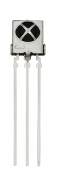
An IR receiver can detect bursts of infrared light sent by a common remote controller (like for a television), and then output a pattern of high/low signals to a Propeller I/O pin. This quick tutorial will first show you how to wire up the infrared receiver. Then, you will run a test program that will display the number for the remote button pressed in the Serial Terminal.
Activities with an infrared receiver are sensitive to interference from other light sources, including sunlight and fluorescent light fixtures.
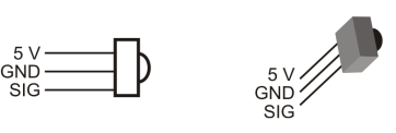
The infrared receiver needs three connections: 5 V, GND, and an I/O pin to read the signal it sends. The circuitry inside the infrared receiver makes it safe to connect its signal pin to the Propeller I/O pin with a small resistor, even though the sensor is powered by 5 V.
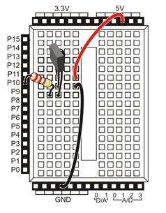
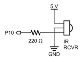
You can use the schematic with any Propeller board that has a prototyping area.
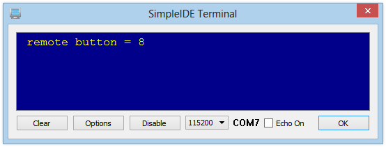
The test program decodes signals received from a SONY remote. In the SimpleIDE terminal, it displays the value of whichever button you press on the remote.
You should see the remote button number displayed in the SimpleIDE terminal. Note that the Channel up/down, Volume up/down, and Mute buttons also return numbers.
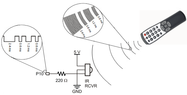
The IR receiver is looking for infrared light (in the 980 nanometer range) that is pulsing at around 38 kHz. The IR remote sends short bursts of 38 kHz infrared light, in a different on-off pattern for each button on the remote. While the IR receiver detects these bursts it sends a 0 the Propeller I/O pin, and a 1 when it does not. The sirc library does the work of decoding the on-off pattern detected by the I/O pin. The name “sirc” stands for SONY Infrared Remote Code, since it decodes signals that use the SONY remote protocol. This is why you must use a remote that is set up to control SONY devices.
The test program very short. It calls two functions from the sirc library: sirc_setTimeout (int ms) and sirc_button(int pin).
The function sirc_button sets the specificed I/O pin to input, decodes any incoming infrared signal detected, and returns a value matching to the IR remote button that was pressed. If there is no value returned within the number of milliseconds set by the sirc_setTimeout function, sirc_button will return a -1.
Inside the while(1) loop, a single print statement contains the call to sirc_button, and displays the return value in the Serial Terminal. Each time through the loop, the HOME formatter moves the cursor to the upper left corner of the SimpleIDE terminal, and the CLREOL (clear to end of line) formatter refreshes the printed string with the most recent value returned by sirc_button. The loop repeats about 10 times per second, since pause(100) introduces a 100 ms delay each time through.
/*
  Test SIRC Remote.c

  Connect 38 kHz IR receiver to Propeller P10
  Decodes button presses on Sony-compatible IR remote
  Run with Terminal

*/

#include "simpletools.h"                      // Libraries included
#include "sirc.h"

int main()                                    // main function
{
  sirc_setTimeout(1000);                      // -1 if no remote code in 1 s

  while(1)                                    // Repeat indefinitely
  {
                                              //  decoding signal from P10
    print("%c remote button = %d%c",          //  Display button # decoded
          HOME, sirc_button(10), CLREOL);     //  from signal on P10

    pause(100);                               // 1/10 s before loop repeat
  }
}
Interference call! Infrared receivers are sensitive to interference from other light sources, including direct sunlight. Some fluorescent light fixtures can emit 38 kHz infrared light as well. Want to test your light fixtures? See the Your Turn section below for tips on making an Interference Detector.
If you are doing this tutorial, you probably want the IR remote to make your project do something. So, let’s make the IR remote control the LEDs on the Activity Board (original or WX version). First, you will need to add a local variable, and set it equal to the number returned by the sirc_button function call. Then, add a series of if(button… statements that turn the Activity Board’s built-in LEDs on and off, depending on which remote button is pressed.
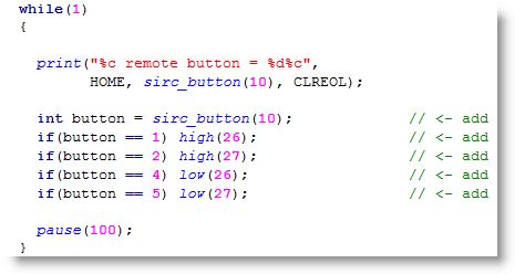
For this, use an if…else if statement that turns on just the P26 LED if the button variable is not equal to (!=) -1, and otherwise turns the LED off. You can use any button on the IR remote to test if it is working — any button should turn on the LED. Then, if you load your program to EEPROM and use an external power supply, you can have a mobile IR Interference Tester. This can be useful scope out different places you might want to use your IR remote controlled inventions.
A VGA display can add a nice touch to projects where you would like sensor information to be displayed without having to keep your project connected to your computer. It’s a spiffy upgrade for apps that currently display their info with LCDs. Monitors and televisions with VGA inputs are commonplace; if you don’t have one at home they are easy to find in second-hand stores.
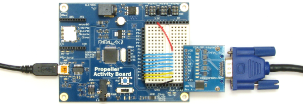
Since the Propeller microcontroller can generate its own video signals, adding a VGA display to a project is pretty simple. The VGA SIP Adapter simplifies wiring to a breadboard or thru-hole board. The vgatext library displays messages with a few simple function calls. This activity shows how to connect the VGA SIP Adapter as well as how to display and customize messages with the vgatext library.
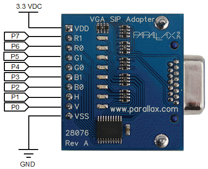
The VGA SIP Adapter has two power and eight signal connections. The power connections are labeled VDD (+3.3 V supply) and VSS (0 V ground supply). The VSS to GND connection is required for sending VGA signals. The VDD to 3.3 V connection is optional for powering the signal indicator LEDs.
The eight signal connections are labeled R1, R0, G1, G0, B1, B0, V, and H. The Propeller sends red, green, and blue pixel signals to the R, G, and B lines, and vertical and horizontal refresh signals to the V and H lines.
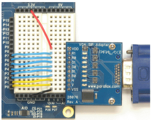
These eight signal lines must connect to a contiguous group of eight Propeller I/O pins, starting with P0, P8, P15, or P24. The vgatext library expects to have the vertical V pin connected to the lowest pin number in the group, and the rest of the pins get connected in order upwards. As you can see in the circuit below, V is connected to P0, H is connected to P1, and so on up through R1, which is connected to P7. Although we could have used P8…P15, we chose P0..P8 for our Activity Board (original or WX version) example, to leave the P12…P15 connections available for connecting servos, Ping))) sensors, or other devices to the servo ports.
Update your vgatext library first! This activity requires the vgatext library updated on 2014-02-13, or later. If the last update listed in the update history of…Documents/SimpleIDE/Learn/Update Your Learn Folder.html is older than 2/13/2014, go to the Update Your Learn Folder page.
Other Propeller Boards: This activity should work on any Propeller development system with a prototyping area. If your Propeller board already has a VGA connector, you can use it instead to try the vgatext library in this activity, but you may need to adjust vga_open() in the example programs to accomodate boards that use different I/O pin groups.
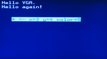
The Hello VGA test code should generate the messages shown below on your VGA display. Two of the messages will have white text on a blue background, and the third will have dark green text on a light green background.
If you look at the VGA SIP Adapter, the B LEDs should be quite bright since the most of the displayed pixels are blue. The R and G LEDs won’t be as bright because their signals are only contributing to the other colors, of which there isn’t much. For example, white is displayed as mixture of red, green and blue, but there are only a few of those characters on this display. The yellow H and V sync LEDs will stay the same brightness regardless of the screen color because those signals have to keep going at a constant rate to control which pixels get updated and when.
/*
  Hello VGA.c

  Test some of the vgatext library's features with a VGA display.

  http://learn.parallax.com/propeller-c-simple-devices/vga-text-display
*/

#include "simpletools.h"                      // Library includes
#include "vgatext.h"

vgatext *vga;                                 // VGA identifier

int main(void)                                // Main function
{
  vga = vgatext_open(0);                      // Open VGA port with P0 base

  dprint(vga,"Hello VGA.\n");                 // Message + newline
  dprint(vga,"Hello again!\n");               // Another message

  vgatext_setXY(3, 4);                        // Set position
  vgatext_setColors(5);                       // Set color palette

  dprint(vga, "* <- x=3 y=4 color=5");        // Text at position in palette
}
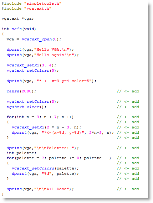
After the code comments, #include “vgatext.h” adds access to the vgatext library’s functions. As usual #include “simpletools.h” is also present. In this example, it gives access to dprint, which makes displaying text on the VGA display almost as convenient as it is with SimpleIDE Terminal.
Next comes vgatext *vga; Like many other text devices, the VGA terminal needs a device identifier that can be passed to functions like dprint to differentiate it from other text devices that might be connected to the Propeller. It’s best to declare this before main and outside of any functions. This way if you add more functions to your project, they’ll all have access to the vga identifier.
The first item inside the main function is vga = vgatext_open(0). The vgatext_open(0) part tells the vgatext library that the eight VGA connections start at P0. (If you were to instead move all the connections upward so that they occupied P8 to P15, you’d have to change it to vgatext_open(8).) Setting this function call equal to vga completes the association between the library and the hardware.
The code is now ready to use the vga device identifier with functions such as dprint to display messages like the ones shown in the next two lines. In dprint(vga,”Hello VGA.\n”) and the “Hello again!” message that follows it, the \n operator works the same way you’d expect it to in SimpleIDE Terminal.
The vgatext library has functions for setting cursor positions and choosing up to 8 different color schemes for character printing. The vgatext_setXY(3, 4) statement positions the cursor so that the next character that gets printed will appear at space 3 and row 4 from the top-left corner. Keep in mind that it starts counting from zero, so it’s really the fourth space and fifth row.
The vgatext_setColors(5) statement changes the color scheme from its default of 0 for white text on blue background to 5, which is dark green text on a light green background.
After those two statements, the last dprint places an asterisk at space 3, row 4, and prints its entire message with color scheme 5.
Libraries are for Reading — Read the vgatext library’s documentation to learn more about these special features. In SimpleIDE, click Help, then Library Reference, and find the vgatext link in the list.
Display Area — The VGA library makes your monitor 30 characters wide by 14 lines high.
Display Formatters — You can clear the screen with dprint(vga,”%c”, CLS), and HOME also works. You can also use values like 8 for backspace, 9 for an 8-space tab, and 13 for return. Not all of the constants are identical to the SimpleIDE Terminal, though. For example, the value 11 is the same as CLREOL (clear to end of the line) in the SimpleIDE Terminal, but the VGA library uses 11 for setting the cursor’s Y position.
Palettes & Special Features —The vgatext library has functions for special features like custom color schemes (the documentation calls them “palettes”). It also has getX, getY and others.
Output Functions — You can also use output functions in the simpletext library that have a text_t device parameter. The dprint function is just one example.
Let’s add some code that waits two seconds, clears the display, and then makes these messages appear.
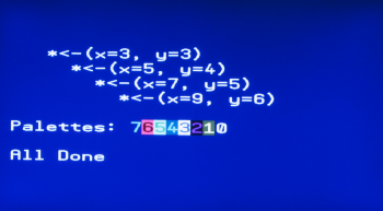
Note that vgatext_setColors(0) resets the display to its original color scheme. Without calling that before vgatext_clear, you’d end up with a light green background because that was the program’s previous color scheme. Insetad of using constants like 3, 4, and 5, the two loops you added are using variables to select a variety of cursor positions and color schemes.
Write a for… loop that displays a variable’s value as int counts from 20 to 1 on the same line. Unless you think it through carefully, you might end up with a surprise when the values get to 9 or lower. How will you fix that surprise? Hint: One solution would be to add a call to vgatext_clearEOL. Another solution might be to use one of the simpletext library’s functions that support printing a fixed number of characters.
An acceleration meter (accelerometer) senses the forces that acceleration and gravity exert on a small mass inside the sensor. Think about that feeling of being pressed into your seat back as your car speeds up rapidly. Now think about the feeling of how gravity pulls you to the ground. Those are examples of the forces that an accelerometer senses and reports.
Accelerometers come in single-axis, two-axis (also called dual-axis), and three-axis varieties. If your application is just measuring the acceleration forces in a drag-racing car driving straight ahead, one axis is all that’s needed for sensing the forward/backward acceleration of speeding up and slowing down. A car driving a flat course with turns can probably be measured with a two-axis accelerometer to sense both forward and backward acceleration and the acceleration involved in left and right turns. If you add hills and banked turns or any other three dimensional measurements into the mix, a three-axis accelerometer becomes the best choice.
In this activity, we’ll use the Propeller microcontroller to measure the effect of gravity on the MMA7455 3-Axis Accelerometer Module.
For this activity, we’ll use the Parallax MMA7455 3-Axis Accelerometer Module and some jumper wires to connect it to 3.3 V, ground, and Propeller I/O pins.
In addition to 3.3 V and GND, this circuit has three connections for SPI communication: DATA, CLK, and /CS.
To learn more about the DATA, CLK, and /CS connections and what they do, see the Simple Protocols – SPI Example tutorial. It uses this same 3-axis accelerometer.

The schematic will work with any Propeller board that has a prototyping area.
The test code makes the Propeller display all three acceleration axis measurements:

Here is an example of some un-calibrated accelerometer measurements with the board sitting flat on a table. Since this sensor and yours are both un-calibrated at this point, your values may be a bit different from what’s shown here. After calibration, it should read x = 0, y = 0, and z = 64. Reason being, when an accelerometer is sitting flat on a table, it should be sensing force exerted by gravity on its z axis, which is about 1 g (g for gravity, not gram), and no forces on the x and y axes. If you turn the board over so that it is face-down instead of face-up, the z axis should hit the bottom of its measurement range with some negative value. Setting the board on various edges, perpendicular to the table will result in max/min values for the x and y axes.

This program includes the mma7455.h library for access to its functions. First, short x, y, z; declares a 16-bit global variable for each sensing axis; these variables will be used by the MMA7455_getxyz10 function later. Inside main, the call MMA7455_init(7, 8, 6) passes a number to each of the functions 3 parameters for telling the library which Propeller I/O pins you connected to the MMA7455’s DATA, CLK and /CS pins. In the main loop, the call MMA7455_getxyz10(&x, &y, &z) passes the address of each axis variable to the function. The function then loads measurement values into each variable.
/*
  Test MMA7455.c

  Test the Parallax MMA7455L 3 Axis Accelerometer module.

  https://learn.parallax.com/propeller-c-simple-devices/mma7455-three-
  axis-accelerometer
*/

#include "simpletools.h"                      // Include simpletools header
#include "mma7455.h"                          // Include mma7455 header

short x, y, z;                                // Axis variables

int main()                                    // Main function
{

  MMA7455_init(7, 8, 6);                      // I/O to: DATA, CLK, /CS

  while(1)                                    // Main loop
  {

    MMA7455_getxyz10(&x, &y, &z);             // Get acceleration measurements
    print("%c x=%d, y=%d, z=%d  %c",          // Display measurements
           HOME, x,    y,    z, CLREOL);

    pause(200);                               // Wait 200 ms before repeat
  }
}
After that, print(“%c x=%d, y=%d, z=%d %c”, HOME, x, y, z, CLREOL) sends the cursor to SimpleIDE Terminal’s top-left HOME position. Next, it displays the decimal-integer value of the x, y, and z variables, and then clears all characters to the right. After that, pause(200) waits 200 ms before allowing the main loop to repeat.
Acceleration (a) — the change in speed over time.
Gravity (g) — the attraction between objects that can result in acceleration.
Force (f) — think of it as the push-pull interaction between objects.
Mass (m) — physical matter of an object. Both gravity and acceleration exert forces on masses.
Accelerometer — An accelerometer senses the force that gravity applies on its sensing mass, and reports it as 1 g (one gravity’s worth) of acceleration. To get that same force from a vehicle seat back, it would have to speed up as fast an object accelerates when you drop it (in free fall).
Check Out the Library — The mma7455 library has functions for calibration, measuring over different g ranges, and more. For more info, check …MMA7455 TestlibMMA7455Documentation MMA7455 library.html
You can calibrate each axis so that your MMA7455L reports zero when the axis is perpendicular to the earth’s gravity and not accelerating in any direction. For example, with the board flat on a level table, both the x and y values should be zero, and when the board is on its edge, perpendicular to the table, the z axis should be zero. The MMA7455_setOffsetX function can fix that, and there’s also a Y and Z version. Adding them to Test MMA7455.c can fix the offset. Start with twice the value you would want to add to get it to report zero. Re-test and fine tune from there.

Want to know how just how tall a building or a tree really is? You can sight the top of the object along the edge of your Activity Board, and measure the tilt angle. That angle and your distance from the object (labeled Adjacent in the picture below) are all the ingredients you’d need calculate the height.

In a right triangle, the angle θ is equal to the opposite side divided by the adjacent side. Multiplying both sides by the adjacent distance results in an expression for solving the opposite height. It’s the adjacent distance multiplied by the tangent of the angle.

After determining the opposite height (shown in above), all you have to do is add to that the height at which you held the accelerometer when you took the measurement.

Let’s say that the adjacent distance to an object is 10 m, and at that distance the accelerometer was held 1.5 m from the ground to get the line of sight of the top of an object. The angle reported by the accelerometer unit was 61°. From this, we can estimate the height of the object to be 19.54 m, as shown below.

The board needs to be perpendicular to the ground (on its edge and not tilting forward/backward) for the sight measurement to get a good angle. In other words, x and y are used for the θ angle measurement, and we want to make sure z stays at zero.
Here is one way to modify the example code that calculates the x/y tilt angle, and it also reports the z tilt.

After that, convert to float, and opposite and object height equations for automating the height calculations.
If the zf value is larger than 64.0, the asin(zf/64) will return the nan (not a number) value. The if(isnan(angleZ)) statement checks if this happened, and prints a message if it did, or the result value if it didn’t.
A PIR Sensor can tell when something nearby moves. The sensor detects the pattern of infrared energy in its surroundings. If the pattern changes, the sensor outputs a high signal. The Propeller microcontroller only needs to monitor this signal with an I/O pin to know if something is moving around nearby.
(1) PIR Sensor Rev B (#555-28027)
(1) 220 ohm resistor
(3) jumper wires
The PIR sensor connects to 3.3 V, ground and a single Propeller microcontroller I/O pin. (The 220 ohm resistor isn’t strictly necessary, but it could help protect the sensor from an accidental signal sent from the Propeller I/O pin, which could happen from wiring or coding errors.)
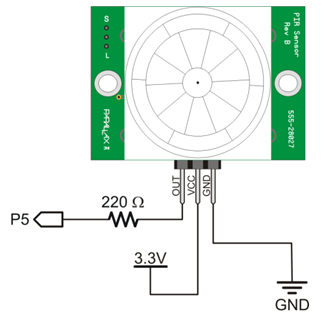
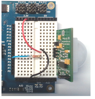
Note: The circuit and example code in this tutorial also work with the PIR Mini (#28033). Connect its Out pin to P5, its VDD pin to 3.3 V, and its GND pin to ground.
The following program continuously checks and prints the output state of the PIR sensor.
If you haven’t already installed the latest USB driver, SimpleIDE, or Learn folder, go to Propeller C – Set up SimpleIDE.
/*
  PIR Rev B.c
*/

#include "simpletools.h"                      // Include simpletools library

int main()                                    // Main function
{
  while(1)                                    // Main loop
  {
    int state = input(5);                     // Check sensor (1) motion, (0) no motion
    print("%c state = %d%c\n",                // Display sensor
           HOME, state, CLREOL);
    pause(200);                               // Pause 1/5 second before repeat
  }
}
First, this program includes the simpletools library for its print, pause, and input functions.
The code is entirely inside an infinite while(1) loop. The statement int state = input(5); means “check I/O pin P5 (which is connected to the PIR sensor) and store the result in the local int variable named state.”
If the I/O pin detects 3.3 V, the PIR sensor detected motion and a 1 is stored in state. If the I/O pin detects 0 V, no motion was detected and a 0 is stored in state.
Next, a print statement displays the value of state in the SimpleIDE Terminal. The %c formatter in the string is needed for the HOME and CLREOL control characters. HOME returns the cursor to the upper left position before printing the text and value of state. CLREOL means “clear to end of line” which erases any other characters that may be on the same line in the terminal. Together, these let the display use just one line and update cleanly.
Finally, pause(200) slows down the loop a little bit.
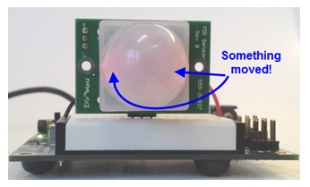
What’s that glow? — A faint red glow from two LEDS inside the PIR Sensor Rev B’s white dome indicates that the sensor is triggered. It is typical for the sensor to be triggered when it is first powered up and getting an infrared reading from its environment. Once triggered by start-up, or by a moving object, the sensor stays in that state and sends a high signal for several seconds.
Passive Infra-Red — That’s what PIR stands for. The sensor is passively relying on infrared light/heat naturally emitted from surrounding objects. It is not actively sending out infrared signals and looking for a reflection, as some other types of infrared object sensors and line followers do.
Automatic Lights and Alarm Systems — If you have an night light that comes on automatically when you walk near it, there’s likely a PIR sensor inside. Also, PIR motion sensors are sometimes used alone or with other types of sensors in security systems to detect intruders.
You may noticed that if you make just a quick movement, the sensor stays in its triggered state for several seconds even if everything is still again. The example code above checked the sensor’s output about every 200 ms. That is more frequent than needed once the sensor is triggered, and maybe not frequent enough if you want your system to respond immediately to a detected motion. Also, it might be helpful to see how many times the sensor has been triggered. The changes below take care of all these issues.
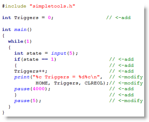
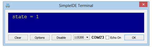
Now, the outer while(1) loop repeats faster, since pause(200) was reduced to pause(5). But, if the sensor is triggered, a pause(4000) in the if… statement keeps the message from printing repeatedly while waiting for the sensor to clear from its high state. You can adjust this pause time if your sensor is still printing more than once from a quick motion.
Make your Activity Board (original or WX version) an audible motion alarm disconnected from your computer. Here are some suggested hardware and software changes:
Now, your battery-powered motion sensor is ready set up and turn on to stand guard any place you want to take it!
RFID stands for Radio Frequency Identification. The Parallax RFID Reader Serial + Tag Sampler includes several unique RFID tags. This tutorial will show you how connect the RFID Card Reader to the Propeller microcontroller. Then, it will show you how to read a tag’s ID number and use that data in a program.
In addition to 5V and ground, the RFID Card Reader – Serial requires two Propeller I/O pin connections. P2 will be set to output, to set the RFID Reader’s Enable pin. P1 will be set to input, to read the serial data coming from the RFID Reader. A 2.2 k-ohm resistor is used for this connection since the reader outputs a 5 V signal and the Propeller chip is a 3.3 V device.
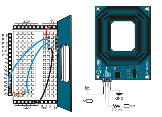
This circuit and test code will work with any Propeller development board that has a prototyping area.
Library Alert! This example code and library requires the Learn folder released 5/15/2014 or later. Update your Learn Library.
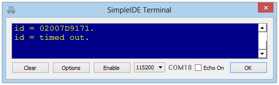
Each tag’s ID number should appear in the SimpleIDE Terminal. If no tag is detected within one second, you will see “timed out” until a tag is detected.
First, the program includes the simpletools and rfidser libraries. The rfidser library gives us access to the rfid_open and rfid_get functions, along with other conveniences for communicating with the RFID reader.
#include "simpletools.h"                      // Include simpletools
#include "rfidser.h"                          // Include rfidser
Next, the program declares two int values, giving names to the two Propeller I/O pins that are connected to the RFID Reader. Later, these names will be passed to parameters in a function call.
int rfidEn = 2;                               // Reader /ENABLE pin to P2
int rfidSout = 1;                             // Reader SOUT pin to P1
The next line creates a device identifier for the RFID reader; we named it rfid. The device identifier is a nickname for a memory structure being set aside to store information about this particular RFID reader connection. If you are using more than one RFID reader in your project, you would give each one its own identifier using rfider *nickname.
rfidser *rfid; // Set up device ID
Inside the main routine, the rfid_open function call starts the RFID card reading process in another cog. Notice that the I/O pin names declared above are passed to the rfid_open function’s parameters. The function returns information that gets stored in the memory structure we nicknamed rfid. Now, rfid is ready to use with other function calls.
int main()                                    // Main function
{
  rfid = rfid_open(rfidSout, rfidEn);         // Open reader, start reading
The last two lines are inside an infinite while loop. The first line gets the tag ID from the reader (if one is detected) and the second line prints the tag ID in the SimpleIDE Terminal.
  while(1)                                    // Main loop
  {
    char *str = rfid_get(rfid, 1000);         // Wait up to 1 s for card
    print("id = %s.\n", str);                 // Print ID.
  }
}
Let’s look closer at those two lines. The function call rfid_get(rfid, 1000) is listening to the device we named rfid for 1000 ms. This function returns the tag’s ID number if one is present, or the phrase “timed out” if no ID number is received within 1000 ms. On the other side of the equal sign, char *str names a pointer to a place in Propeller memory to start storing the characters returned by the function call.
The print function call uses the %s formatter to display str. This formatter will print a character string stored in memory, starting at the address named str. The character string will display as a tag ID or the phrase “timed out” on a new line each time through the loop.
Passive Tags — These tags are passive, meaning they do not have a power source of their own inside. Instead, an embedded antenna circuit inside the tag gathers a tiny bit of power from a magnetic field generated by the Reader. Holding the Reader close to the tag powers it just enough to transmit its ID number back to the Reader with a weak RF signal. This is called an ARPT (Active Reader, Passive Tag) system.
Keep it In the Family — The Parallax RFID Card Reader works with the EM4100 family of read-only tags. This reader will not work with tags from other families, nor can it write data to RFID tags.
When RFID tags are used in access systems, the usual goal is to find out if a tag’s ID is known to the system, so the appropriate action can be taken. The next example program uses if…then…else to take a different actions based on a tag’s ID. First, you will need to write down your tags’ ID numbers.
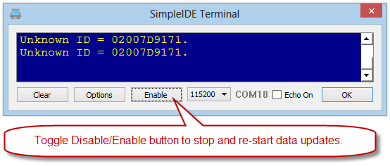
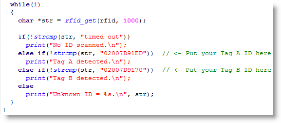
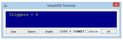
Now that the program recognizes both tag IDs and takes separate actions for each, you can modify those actions to make the application more interesting. The rfidser library has an rfid_disable function that will make the RFID reader ignore tags until you either re-run the program or call the rfid_enable function. Let’s modify the program to go into lock-down if Tag B is detected.
Rfid_disable;
Print(“Banned user detected – system in lockdown.\n”);
Disable vs Close, Enable vs Open. rfid_disable does not shut down the Propeller core running the RFID reading process that was launched with rfid_open. Reading can resume with rfid_enable. If you want your application to stop reading tags and also free up the Propeller core and memory that it is using, shut down the process entirely with rfid_close. If your project needed to read tags again after that, your program would need to call rfid_open to re-start the RFID reading process again in another core.
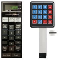
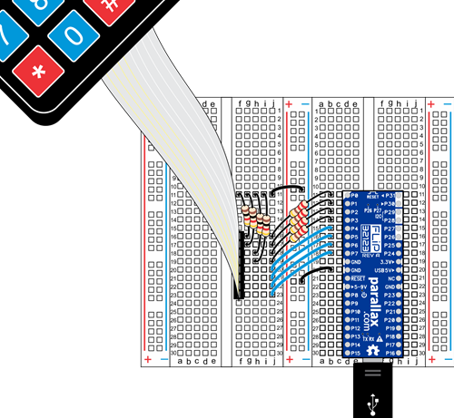
A matrix keypad is the kind of keypad you see on microwave ovens, gas pumps, and calculators. A matrix keypad you can connect to a breadboard is also great for prototypes and inventions where things like codes, times, or other values have to be entered.
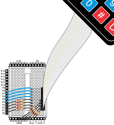
Note: Be careful when making your 4×4 Keypad connections. The FLiP and ABWX diagrams below use the same pins, but the orientation of your circuit and keypad differs depending on which board you use.
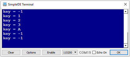
The test program updates the Terminal showing whichever single key is pressed, every 1.5 s. If you’re not pressing a key when it checks, the program will display -1. So, for best results, press and hold the key you want to try. Keep in mind, this is just test code. The Try This and Your Turn examples will demonstrate how to make it responsive as you type in numbers, how to do simple mathematic functions, and more.
Before running the program, let’s add the matrix keypad examples and library to your Learn folder.
Now, you’re ready to try the first example program
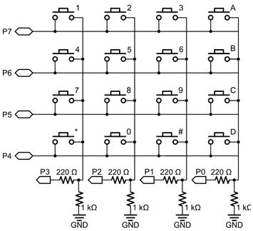
This 4×4 matrix keypad has 16 built-in pushbutton contacts connected to row and column lines. A microcontroller can scan these lines for a button-pressed state. In the keypad library, the Propeller sets all the column lines to input, and all the row lines to input. Then, it picks a row and sets it high. After that, it checks the column lines one at a time. If the column connection stays low, the button on the row has not been pressed. If it goes high, the microcontroller knows which row (the one it set high), and which column, (the one that was detected high when checked). See the schematic in the “Circuit” section, above, for a visual reference of the keypad layout.
The keypad library supports pretty much any number of rows and columns. So, the program has to tell it our keypad is has 4 rows and 4 columns, which I/O pins the lines are connected to, and what value each button represents. The rows, cols, and values arrays store that information. The rows array will be used to tell the keypad library that the top row is connected to P7, the second row to P6 and so on. Likewise, the cols array lists the leftmost column as connected to P3, the next over connected to P2 and so on. The values array stores the value we want the program to give us for each button press. For example, if the top-left button is pressed, we want the number 1, and if the next one over is pressed, we want the number two. If the top right button is pressed, we want the ASCII code for the ‘A’ character, which is 65.
Inside the main function, keypad_setup gets the number of rows (4), the number of columns (also 4), the rows array, the cols array, and the values array. After that, key = keypad_read() will return -1 if no buttons are pressed. If a button is pressed, it will return the value from the array that corresponds to that button. For example, if you press a button on the 3rd row, second column, the keypad_read function will return the number 8, which will get stored in the key variable. To display it correctly, an if statement checks for values less than or equal to 9, and displays them with %d, decimal-integer formatting flag . The ASCII codes for ‘*’, ‘#’, ‘A’, ‘B’, ‘C’, and ‘D’ are 35, 42, 65, 66, 67, and 68, all of which are above 9, and get displayed with the print statement that uses the %c character formatting flag.
/*
  Keypad 4x4 Read Keys.c
  Demonstrates how to read individual key presses with the keypad library.
*/

#include "simpletools.h"                      // Libraries simpletools & keypad
#include "keypad.h"

int rows[4] = {7, 6, 5, 4};                   // Row I/O pins (top to bottom)
int cols[4] = {3, 2, 1, 0};                   // Column I/O pins (left to right)

int values[16] = {  1,   2,    3,  'A',       // Values for each key in the 4x4
                    4,   5,    6,  'B',
                    7,   8,    9,  'C',
                  '*',   0,  '#',  'D' };

int key;                                      // Variable stores keypad key

int main()                                    // Main function
{
  keypad_setup(4, 4, rows, cols, values);     // Setup dimensions, keypad arrays

  while(1)                                    // Main loop
  {
    key = keypad_read();                      // Get pressed key (or -1 for none)

    if(key <= 9)                              // Display key value
      print("key = %d\r", key);               // If <= 9, dispaly as decimal
    else
      print("key = %c\r", key);               // Otherwise, display as character
    pause(1500);                              // Wait 1.5 s before repeat
  }
}
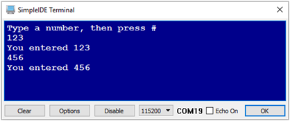
If you want the Propeller to rememeber a value 123 when after you press the 1, 2, and 3 buttons, here’s how it works:
This example program allows you to press/release digits to build numbers. For example, if you press and release 1, then 2, then 3, then #, the program will display “You entered 123”. Keep in mind that it’s not just rememebering the digits 1, 2, and 3, it’s creating the number 123 by multiplying what’s already in the number variable by 10, and then adding the most recently pressed digit. Once the Propeller has this value, it could be used as a count-down timer in an oven, or the first value used in a calculator operation.
/*
  Keypad 4x4 Digits to Numbers.c
  Demonstrates how to build numbers with multiple key presses.
*/

#include "simpletools.h"                      // Libraries simpletools & keypad
#include "keypad.h"

int rows[4] = {7, 6, 5, 4};                   // Row I/O pins (top to bottom)
int cols[4] = {3, 2, 1, 0};                   // Column I/O pins (left to right)

int values[16] = {  1,   2,    3,  'A',       // Values for each key in the 4x4
                    4,   5,    6,  'B',
                    7,   8,    9,  'C',
                  '*',   0,  '#',  'D' };

int number = 0;                               // Stores number result

int main()                                    // Main function
{
  keypad_setup(4, 4, rows, cols, values);     // Setup dimensions, keypad arrays

  print("Type a number, then press #\r");     // User prompt

  while(1)                                    // Main loop
  {
    number = keypad_getNumber();              // Get number entered on keypad

    print("\r");                              // Next line
    print("You entered %d\r", number);        // Display result
  }
}
However, when you start pressing 3 keys at a time, a keypad like the 4×4 Matrix Membrane, which is designed for individual key presess will sometimes display as if a key was pressed that was not actually pressed.
Many combinations work fine, like 1, 5, 9, and D will all display correctly, as will 1, 4, 7, and *. But, try pressing 1, 2, and 7. The program will tell you that detected 1, 2, 7, and 8. This phenomenon is called ghosting, with the number 8 being the ghost number. Ghosting happens when you press 2 buttons on the same row, and one button on the same column. For example, 1 and 2 are on the same row, and 7 is on the same column as 1. The 7 press travels up to 1, across to 2, and then down the 8 column and is detected there. Some keypads that are designed for multiple, simultaneous key presses have built-in diodes that can prevent this.
Another problem with keypads that are designed for indivdual key presses is called masking. Masking just means that if your program is waiting for a single key press, and you then press and release a second key after the first, the second key is not detected. The change is “masked out” by the keypad circuit.