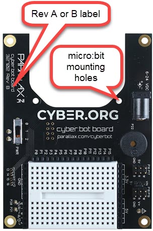
These instructions are for the cyber:bot board Rev A or B. If you have a Rev C board, follow these instructions instead. If you have a Rev A or B board, you are in the right place!
This tutorial will guide you through assembling the cyber:bot, step-by-step. In each step, you will gather a few of the parts, and then assemble them so that they match the pictures. Each picture has instructions that go with it; make sure to follow them carefully.
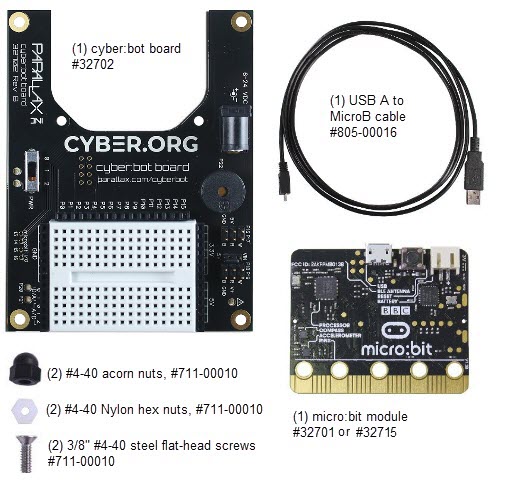
You will need one of the following cyber:bot kit options:
If you have your own cyber:bot conversion kit (#32707) + your own built-up Boe-Bot or Shield-Bot, see this Convert to a cyber:bot instead, then continue with the main tutorial sequence starting with Navigation with the cyber:bot.
You will need to make sure your cyber:bot is ready for programming. Complete these tutorials first
Once you are finished, you will be ready to work through the rest of the main cyber:bot tutorials.
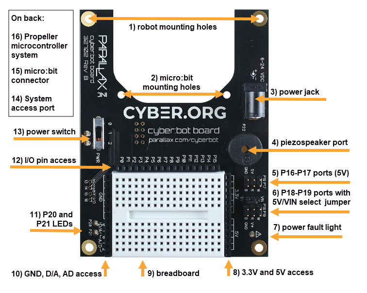
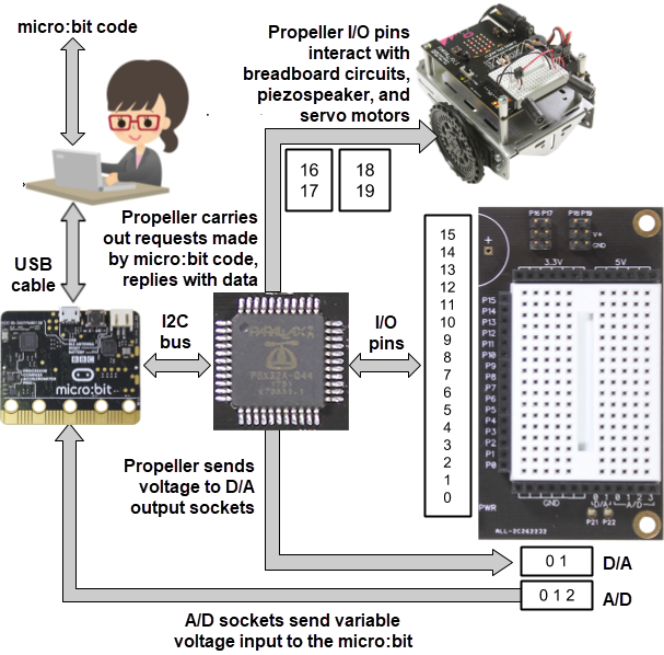
The micro:bit attaches to the cyber:bot board, which is then mounted on the robot chassis. Your micro:bit code communicates with a Propeller multicore microcontroller on the bottom of the cyber:bot board. The Propeller controls the servo motors and interacts with sensor circuits you build on the white breadboard. For a more complete reference, see the cyber:bot board guide.
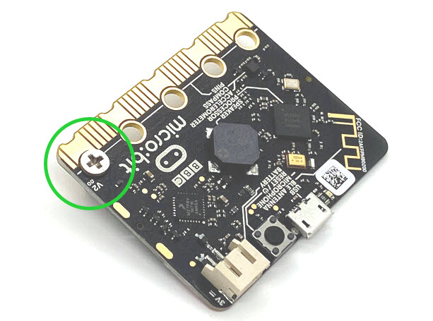
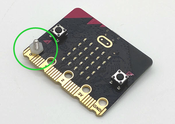
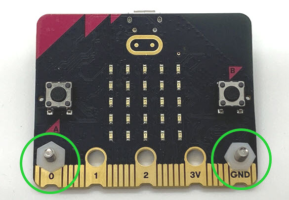
Follow these steps to connect your micro:bit module to your cyber:bot board.

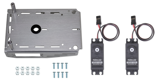
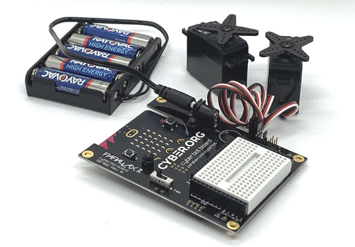
Next, it’s time to build the cyber:bot chassis. In addition to your micro:bit on a cyber:bot board, you will need the parts in the pictures below. If anything is missing, contact sales@parallax.com (888-512-1024). Set aside the bag of electronic components for now.
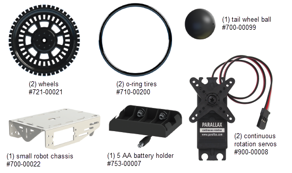
When you are done, you may have some pieces left over. That’s okay!
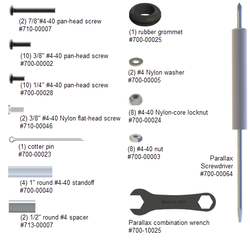
(1) robot chassis
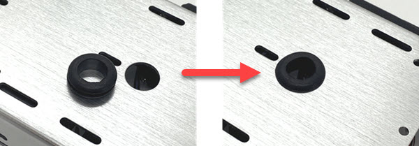
(1) rubber grommet
(2) 1″ standoffs
(2) 1/4″ pan-head screws
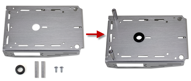
Robot chassis, partially assembled.
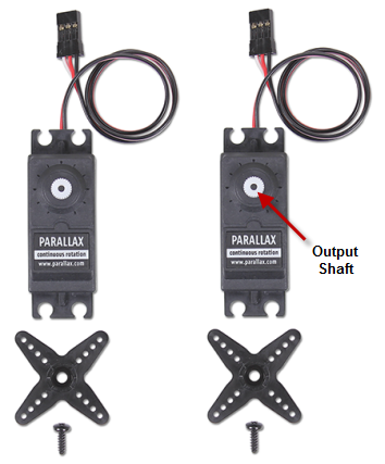
(2) Parallax continuous rotation servos
(8) pan-head screws, 3/8″ #4-40
(8) Nylon core locknuts – OR – regular steel hex nuts
Parallax screwdriver
Parallax wrench
masking tape (optional)
pen (optional)
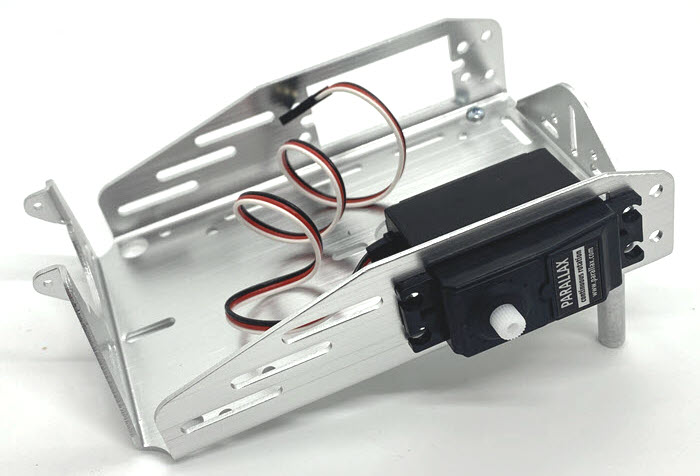
With both servos mounted, your chassis will look like this:
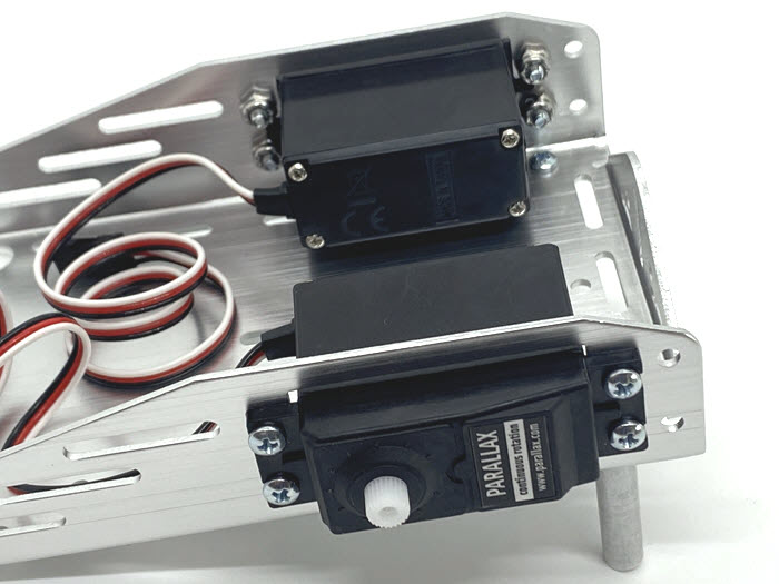
Note: You may mount the servos the other ways instead.
Mounting the servos with the servo shaft closer to the front of the robot is also possible. This design may cause some turning difficulty on “sticky” floor surfaces unless the front of the robot has increased weight. The benefit of mounting the servos this way is that the potentiometer hole in the servo case is more accessible (from the front of the robot). If the servos need to be re-centered, you would not need to remove them from the chassis.
You may also mount the servos with the tabs on the inside of the chassis for a narrower wheel base. This allows for the tightest turns pivoting on one wheel. But, it is easier to remove and replace the servos when they are mounted from the outside.
Throughout this tutorial you may see cyber:bot examples with different servo mounting positions.
(2) – Nylon flat-head slotted screws, 3/8″ 4-40
(2) – 1″ standoffs
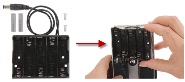
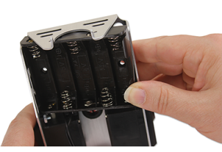
(1) – 5-cell battery pack with 2.1 mm center-positive plug

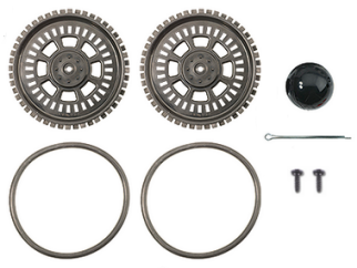
(1) Cotter pin
(1) tail wheel ball
(2) wheels
(2) O-ring tires
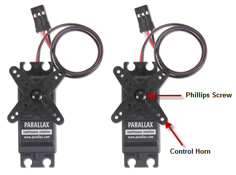
(2) screws saved when removing the servo horns
needle-nose pliers – optional, not included
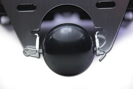
CAUTION – the ends of the cotter pin may be sharp! If you have needle-nose pliers, you can bend the cotter pin ends into a circle to tuck away the points. But be aware that this makes the cotter pin more difficult to remove in the future if you ever want to do that.
The robot’s tail wheel is merely a plastic ball with a hole through the center. A cotter pin holds it to the chassis and functions as an axle for the wheel.
Cyber:bot board with micro:bit installed, servos and battery pack unplugged!
(2) 1/4-inch pan-head screws
(2) 7/8-inch pan-head screws
(2) white Nylon washers
(2) 1/2-inch round aluminum spacers
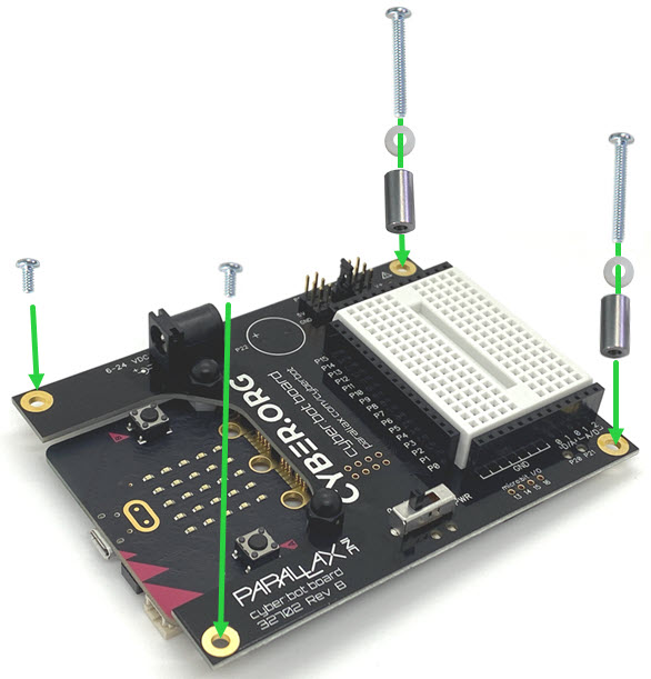
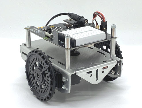
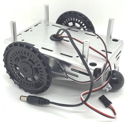
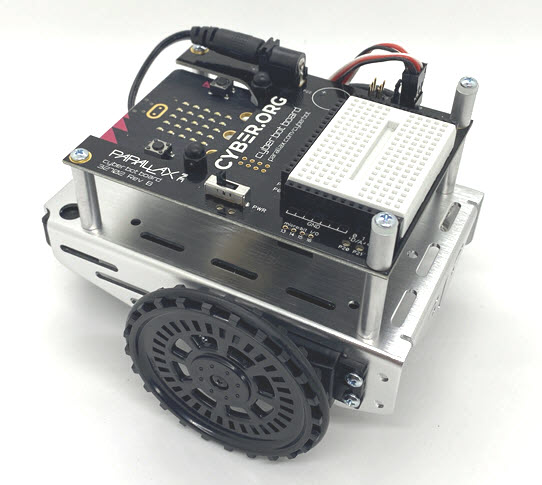
When assembled, your cyber:bot should look like this from the top:
To program your cyber:bot, you will write Python scripts and flash them to the micro:bit as usual. But the micro:bit won’t be working alone. The cyber:bot has two key microcontroller chips that communicate via a pair of circuit lines, one for a common clock and one for data, called an I2C bus.
When your script uses functions from the cyberbot library module, the Nordic chip sends command codes to the Propeller, which then takes action based on the code it received. Using its digital input/output pins, labeled P0-P22, the Propeller controls the servo motors and interacts with circuits on the cyber:bot board. If you have built sensor circuits on the breadboard, the Propeller may also send data back to the Nordic chip.
Now that you have an idea of how the cyber:bot robot’s parts will work together, you are ready for the next tutorial, Navigation with the cyber:bot.
The cyber:bot robot’s drive motors are Parallax Continuous Rotation Servos. Rotation speed and direction are controlled by sending very specific patterns of high/low voltage signals to the servos.
In this activity, you will temporarily attach the servos to the cyber:bot board. Then you will run a script that sends a “stay still” signal to the servo motors. With a screwdriver, you will adjust each servo so it will actually stay still when receiving this signal. This is called “centering” the servos. After this adjustment is done, you will proceed to build the cyber:bot and run test scripts that will turn the servos clockwise and counterclockwise at various speeds.
Parts Required
Tool Required
You’ll need a Parallax screwdriver, or a different Phillips #1 point screwdriver with a 1/8″ (3.18 mm) or smaller shaft.
cyber:bot Library Required!
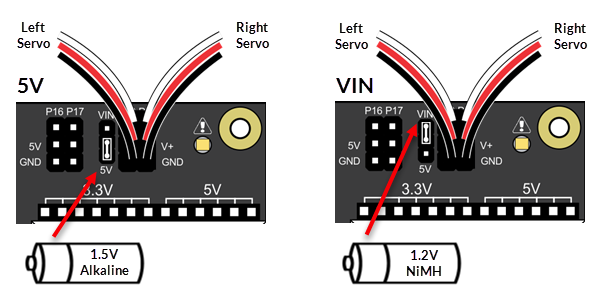
The servo cables plug into the 3-pin P18 and P19 3-pin headers, sometimes called “servo ports,” that are above the white breadboard.
There is a smaller 3-pin header to the left of the servo ports. A shunt jumper connects two pins on it, selecting the voltage source supplied to the servos. The 5V setting limits the voltage to 5V, regardless of the input voltage. The VIN setting supplies the servo with whatever voltage level is connected to the board.
The Continuous Rotation Servos need 4 to 6 VDC to operate. So, the setting you should use depends on the kind of batteries you have.
Missing a Voltage Selection Jumper? Replacements are available – contact our sales department to order part #452-00043; there are three per board.
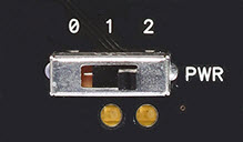
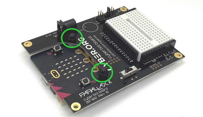
The cyber:bot board has a three-position switch, which allows you to choose whether or not to power the servos when you power the rest of the board. Here are guidelines:
If a servo has not yet been centered, it may turn, vibrate, or make a humming noise when it receives the “stay-still” signal. Once you’ve assembled the cyber:bot, the servos must be removed to be centered again, making this step critical.
# left_servo_stay_still.py

from cyberbot import *

bot(18).servo_speed(0)
On the side of the servo is a small access hole. Inside the hole is what appears to be a small screw. This is a plastic potentiometer adjustment knob.
This short video will assist you with the process of centering the servos:
]
A potentiometer is an electrical device that provides variable electrical resistance. Some potentiometers have a knob for adjusting the resistance, like these servos, while others may have a sliding bar. Either way, the schematic symbol for a potentiometer is the same.
# right_servo_stay_still.py

from cyberbot import *
bot(19).servo_speed(0)