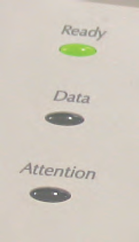
The LED lights in your kit are similar to those commonly used in products to display the device’s status. They can be found on keyboards, monitors, alarm system control panels, and printers like the ones below.
The micro:bit has 25 red LEDs in its pixel array. Those red LEDs contain the same elements; they just come in smaller packages. Larger LED lights are used in traffic lights and automobile break and turn signal lights.
These activities introduce ways to control indicator light behaviors, including rate, timing, and sequencing. You will also use your measuring skills to test the LED light’s micro:bit controlled supply voltage with a voltmeter, and learn to use a new device called an oscilloscope to see the relationship between the LED’s supply voltage over time.
These lessons use a specific kit and build on earlier tutorials.
You will need:
Complete these tutorials first:
You will be able to:
In later activities, you will apply these approaches to “indicate” something that has been sensed. You will also use them to create slow motion versions of signals that control other devices like position controlling servo motors.
In this activity, you will connect the LED circuit to a micro:bit I/O pin and use a script to turn the light on and off. You will also use the script to adjust the on/off rate and number of times it blinks. Last, but not least, you will calculate the timing of the lights. The three most common ways to quantify timing are called period, frequency, and duty cycle.
Let’s begin by re-using the familiar LED circuit, first built in the Breadboard Setup and Testing for micro:bit tutorial. In addition to the basic micro:bit adapter, power rail, and test post setup, it uses the following parts:
(1) LED – green
(1) resistor 220 Ω (red-red-brown-gold)
(1) jumper wire, black
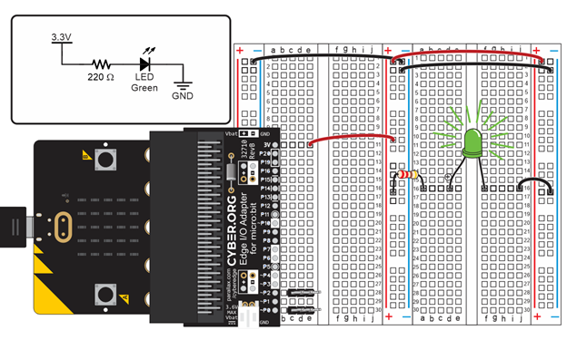
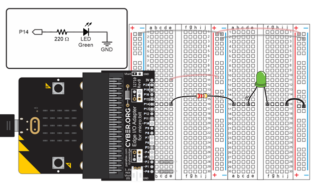
Instead of connecting the LED to the 3V supply rail on the breadboard, this activity requires a connection with a micro:bit I/O pin.
Let’s make the LED blink using a micro:bit script.
# led_blink

from microbit import *

while True:
    pin14.write_digital(1)
    sleep(500)
    pin14.write_digital(0)
    sleep(500)
There are lots of different ways to change the timing in the blinking pattern. Try these examples to understand the cause and effect. To test a change to the script, click Send to micro:bit. Then, check the LED light for a changes.
This animation shows how the led_blink script causes the micro:bit to alternate between connecting P14 to the 3.3 V (+) and GND (-) power connections.
(View full-size: blink-light-script-circuit-how.mp4)
The first statement in the led_blink script’s while True loop is pin14. write_digital(1). This causes the micro:bit to connect P14 to its 3.3 V supply. Since the LED circuit on the breadboard is connected to P14, it turns the light on, just like when you connected it to a socket by the red (+) line in the bus strip. Then, sleep(2500) tells the micro:bit to wait for 2.5 s before continuing. The effect is that the light stays on during that time.
When the script reaches pin14.write_digital(0), it causes the micro:bit to connect P14 to its GND (0 V) supply. This is the same as if you were to connect the LED’s resistor to a socket by the blue (-) line on the bus strip. Since the other end of the LED circuit is also connected to GND, it means there’s no electrical pressure across the LED circuit, so no current flows through it and the LED does not emit light. After that, sleep(2500) leaves the light off for 2.5 s before the while True loop repeats.
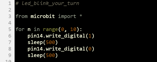
The for …in range(…) loop isn’t just for counting. You can also use it to repeat statements a certain number of times without making use of the value of the counting variable. Here is an example where for n in range(0, 10): makes the light blink 10 times.
In the Tests section, you modified the script to adjust the light’s period, frequency, and duty cycle. Not all lights blink indefinitely, so after this, you will also experiment with script modifications to make the light blink a certain number of times.
On/off signal period and duty cycle matter because they are used to control many devices other than lights. Examples include:
Period is the time it takes for a signal to repeat. Period is measured in seconds and abbreviated with an upper-case T. In the case of your LED on/off signal, it’s the sum of the high (on) and low (off) times.

Example: The LED was on for 0.25 seconds and off for 0.25 seconds. What is the period?
T = tHIGH + tLOW
= 0.25 s + 0.25 s
= 0.5 s
Frequency is the rate at which the light blinks on/off, in repetitions per second. Frequency’s abbreviation is f, and its SI unit for measurements is hertz (Hz). The hertz is named after Heinrich Rudolf Hertz, who did important work to prove the existence of electromagnetic waves. Examples of electromagnetic waves include visible light and radio waves.
Convert period to frequency (and frequency to period) by making the known value the denominator of 1. For example, if you know the time it takes a signal to repeat itself (period T), then the frequency is f = 1 / T. Likewise, if you know the repetitions per second (frequency F), then the period is T = 1 / f.
f = 1 / T T = 1 / f
Example: The period is 0.5 s, what is the frequency?
f = 1 / T
= 1 / 0.5 s
= 2 Hz
Example: The frequency is 2 Hz, what is the period?
T = 1 / f
= 1 / 2 Hz
= 0.5 s
SI units 1 Hz = 1/s. In speaking terms, you can think of 1/s as “one repetition per second or one ’cycle’ per second”.
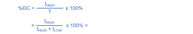
Duty cycle is a measure of how much time a repeating signal stays on (high) during its period. It is commonly abbreviated D, DC, or %DC, and most commonly measured as a percent value. In other words, what percent of the period did the light stay on?
In the Tests section, you experimented with three different combinations of high and low time at 1 Hz:
Example: Calculate the duty cycle for a signal that is high for 200 ms and low for 800 ms.
%DC = [ tHIGH / (tHIGH + tLOW) ] x 100 %
= [ 200 ms / (200 ms + 800 ms) ] x 100 %
= 0.2 x 100 %
= 20 %
Example: Calculate the duty cycle for a signal that is high for 200 ms and low for 800 ms.
%DC = [ tHIGH / (tHIGH + tLOW) ] x 100 %
= [ 500 ms / (500 ms + 500 ms) ] x 100 %
= 0.5 x 100 %
= 50 %
Example: Calculate the duty cycle for a signal that is high for 800 ms and low for 200 ms.
Answer: 80%
With a variable, you can also make a light blink at varying rates. You will try that with the led_blink_variable_rate script.
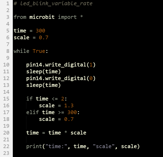
In this example, the time variable controls the on/off times. The time variable is also multiplied by scale variable to increase and decrease the on/off times with each loop repetition. Initially, scale is 0.7, which causes time to decrease with each loop repetition. When time drops to 2 or less, scale gets changed to 1.3. Then, time starts increasing again until scale grows to 300 or more.
from microbit import*

for n in range(0, 20):
      pin14.write_digital(1)
      sleep(750)
      pin14.write_digital(0)
      sleep(500)
from microbit import*

time = 1000
scale = .5

for t in range (2500,0,-100):

    pin14.write_digital(1)
    sleep(time)
    pin14.write_digital(0)
    sleep(time)

    if t <= 1500:
        scale = .75
    elif t > 1500:
        scale = 1

         time = time * scale
A binary value can hold one of two states: 1 or 0. Up to this point, we’ve been using those 1/0 binary values to turn lights on and off with pin14.write_digital(1) and pin14.write_digital(0).
In electronics, digital to analog conversion is used to make things seem like they are analog (varying continuously). For example, with the LED in this activity, you will use the digital values of 0 through 1023 and back to 0 to make the LED light take small steps from dim to bright and then to dim again. The steps will be so small that human eyes cannot perceive them, so it is called “digital to analog conversion”.
The pin14.write_analog() method accepts arguments from 0 to 1023 to set the LED’s brightness from off to full brightness. Here are some examples of write_analog calls that adjust how brightly the P14 LED shines.
pin14.write_analog(1023) # Max brightness
pin14.write_analog(512) # half brightness
pin14.write_analog(256) # quarter brightness
pin14.write_analog(1) # 1/1024th of full brightness
In this activity, you will experiment with write_analog and scripts that control the brightness of the P14 LED. You will also use for loops to make this brightness seem to vary continuously (analog).
For this activity, you will re-use the same setup and LED circuit from Connect and Blink a Light.
This script sets a light to ⅛, ¼, ½, and full brightnesses.
# led_brightnesses

from microbit import *

while True:
    pin14.write_analog(128)
    sleep(1000)
    pin14.write_analog(256)
    sleep(1000)
    pin14.write_analog(512)
    sleep(1000)
    pin14.write_analog(1023)
    sleep(1000)
Remember from the Connect and Blink a Light activity’s On-Off Signals section that a blinking light has a period, frequency, and duty cycle. The period is the total on/off time for a single blink, abbreviated T and measured in s. The frequency is the blinks per second, abbreviated f and measured in Hz. The duty cycle is the percent of the period that the light is on.
The write_analog() method makes the light blink at 50 times per second (f = 50 Hz). That’s faster than the eye can see, but the eye does detect the high time of each blink as brightness. If the light is on for ½ the time, it appears to be half as bright. On for ¼ of the time -¼ as bright, and so on…
Remember that the period is 1/f. In the case of write_analog, the micro:bit sets the light’s blink period to T = 1/50 Hz = 20 ms. You have 1024 options for how long the light stays on during the 20 ms period — from 0/1024ths to 1023/1024ths of the time. For 50% duty cycle (and 50% brightness), use pin14.write_analog(512). That’ll give you 512/1024ths of on time, which is 50%.
Example: Set the brightness to 25%.
Solution: For 25% brightness, we need 25% duty cycle. 0.25 x 1024 = 256, so use 256 in write_analog, like this: pin14.write_analog(256).
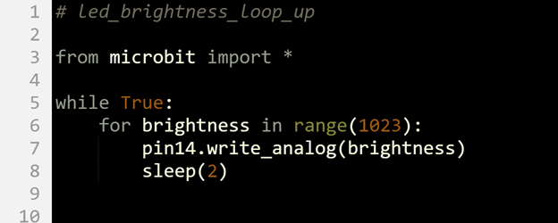
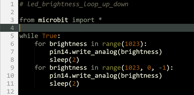
Here is an example that uses a for loop inside a while loop to repeatedly fade-in brightness from 0 to max (1023).
In the physical world, analog quantities like light intensity and audio volume are continuously variable. Think of “continuously variable” as having an infinite number of increments in any range. Like the blue analog line in the diagram. It’ll have values like 514.00… and 515.00…, but between those two levels, there’s an infinite number of other levels. Two examples include 514.33… and 514.66…
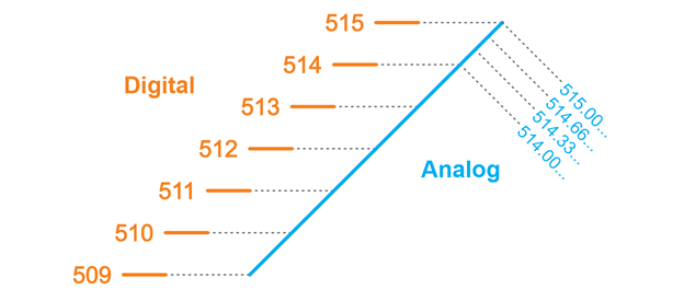
In electronics, analog quantities are represented by digital steps, like the orange 509 through 515 integer steps in the diagram. Many electronic devices store digital step values and use them to synthesize analog values. In addition to the light intensity example we are working with, music and video streaming use digitized audio and video data. But, the steps in the digitized values are so close together that we cannot hear/see the difference.
In the case of the micro:bit, it can set the LED to 1024 different brightnesses (including off). If it increases by one increment at a time, it looks like it varies continuously, but it’s actually stepping from one brightness to the next. Even so, it is commonly called an “analog” setting, and the process of converting a number in the 0 to 1023 range to an LED brightness is a form of “digital to analog conversion”.
Digital to analog conversion devices normally have a number of steps that is some power of two. For example, 1024 is 210. The power of 2 is actually a memory size, measured in “bits” which are memory elements that can store binary digits: 1 or 0. In the case of the micro:bit D/A converter, it’s called a 10-bit digital to analog converter. With 10 bits or memory (10 binary 1/0 digits), you can count from 0 through 1023:
Decimal Binary (10-bit)
1 0000000001
2 0000000010
3 0000000011
4 0000000100
5 0000000101
6 0000000110
7 0000000111
…
509 0111111101
510 0111111110
511 0111111111
512 1000000000
513 1000000001
514 1000000010
515 1000000011
…
1021 1111111101
1022 1111111110
1023 1111111111
Sometimes, it’s helpful to test a small loop to figure out what a larger one will really do. For example, you could use this script to quickly see what the result of a for…in range() loop with one argument will be. Since it prints 0, 1, 2, and 3, it can help verify that it counts from 0 up to, but not including, the value in the parentheses.
for n in range(4):
    print(n)
Another approach would be to look it up in the Python language documentation. For example, the answer is on this page too: 4. More Control Flow Tools. It’s part of the Python 3 Documentation, which is what the MicroPython for the micro:bit is based on.
One way to make the brightness fade in and then fade back out would be to have a loop that counts up, like the one you just tried, followed by a loop that counts back down. Counting down with range needs a start, stop, and negative step value. For example, this for loop counts 5, 4, 3, 2, 1:
for n in range(5, 0, -1):
    print(n)
Extending that to the for brightness loop, you could use for brightness in range(1023, 0, -1). This would start at maximum brightness and count down to a brightness of 1. That loop following the fade-in loop would fade the brightness back out.
Let’s try the fade-in, fade-out effect explained in the try Did You Know section above.
Solution:
from microbit import*

while True:
    for brightness in range(0,1023,10):
        sleep(500)
        pin14.write_analog(brightness)
                sleep(1000)
In this activity, you will:
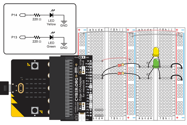
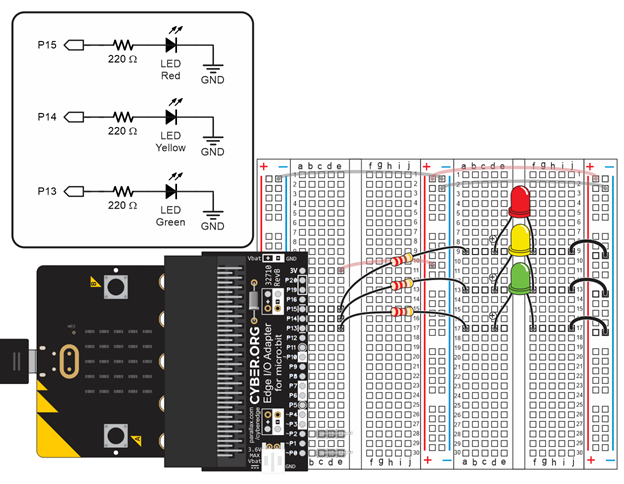
(1) Setup from Connect and Blink a Light including the green LED circuit parts.
(1) LED – yellow
(1) Resistor – 220 Ω (red-red-brown-gold)
(1) Jumper wire (black)
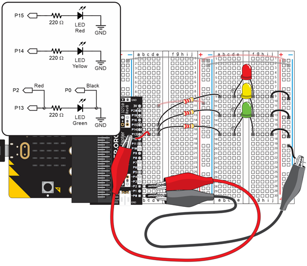
To build the LED circuits in the picture shown below:
This script will test your LED circuits by blinking them on/off together.
# led_blink_x2

from microbit import *

while True:
    pin13.write_digital(1)
    pin14.write_digital(1)
    sleep(500)
    pin13.write_digital(0)
    pin14.write_digital(0)
    sleep(500)
These statements repeat indefinitely inside the while True loop:
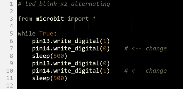
Changing from simultaneous to alternating blinks is pretty simple. All you have to do is change the state argument in two of the pin14.write_digital calls.
Up to this point, it looks like both lights change at the same instant. In reality, the P13 light turned on a tiny fraction of a second before the P14 light. That’s because the micro:bit executes statements in a script sequentially—one after another. Since pin13.write_digital() comes before pin14.write_digital() in the script examples, the P13 light changes first. The P14 light changes an instant AFTER the P13 light.
In the current script, the time between light changes for P13 and P14 is not visible to the human eye. You can make it visible by adding a sleep statement between the two write_digital() calls (along with other changes).
Sequential blinking takes a few more changes since the script has to turn one light on/off, and then turn the other light on/off afterwards. In this approach, the script turns the P13 light on and off first, then follows with the P14 light.
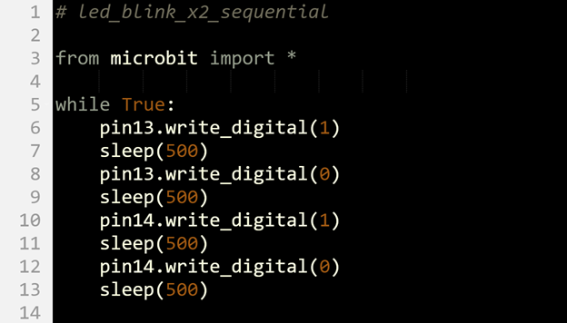
In this activity, you learned how to use the digital_write() method to blink two lights in various arrangements to each other.
Create a script that holds the green LED on while the yellow LED turns on and off. Place the code for the green LED outside the while True() loop.
Solution:
from microbit import*

pin13.write_digital(1)

while True:

    pin14.write_digital(1)
    sleep(500)
    pin14.write_digital(0)
    sleep(500)
In the next activity, you will be adding a third LED light, and then turning them on/off in custom sequences. It’s true that you could extend the coding approach you used for two LEDs, but there’s a better way: lists. (We’ll practice lists using a serial terminal first, so there is no circuit needed for this activity).
A list is a sequence of items contained between brackets, like this:
clist = [’green’, ’yellow’, ’red’]
A script can access an item in a list by using the item’s index value, starting with 0 from left to right. So, the index of ’green’ is 0, ’yellow’ is 1, and ’red’ is 2. The instruction print(clist[2]) would display the word “red” in a serial terminal. A script can also change items a list using index values. For example, to change clist[1] from ’yellow’ to ’blue’ you would use clist[1] = ’blue’.
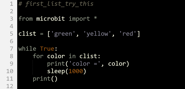
In this activity, you will use lists to display different sequences of printed colors in the terminal. In the next activity, you will instead use the lists to make the colored lights display in various sequences.
There are different ways to display items in a list. This activity will start by displaying items in a list “the hard way” because it’s good to get familiar with how to access items in a list by their index values. The Try This section introduces “the easy way” to access each item in a list with a loop that does the indexing for you. Last, but not least, the Did You Know and Your Turn sections show how to use your script to change, append, and display the contents of lists.
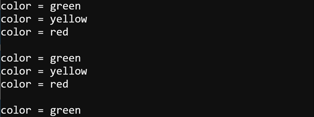
This first script repeatedly displays this in the python.microbit.org Serial terminal.
color = green
color = yellow
color = red
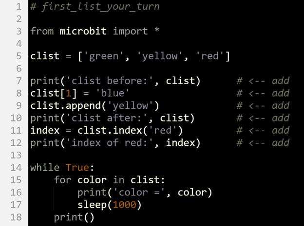
# first_list

from microbit import *

clist = ['green', 'yellow', 'red']
index = 0

while True:
    color = clist[index]
    print('color =', color)
    sleep(1000)
    index = index + 1
    if index >= len(clist):
        index = 0
        print()
In the script, clist = [’green’, ’yellow’, ’red’] creates a list with three items: clist[0] is ’green’, clist[1] is ’yellow’, and clist[2] is ’red’. The value of the index variable starts at zero. Inside the while True loop, color = clist[index] stores ’green’ in color when index is 0, ’yellow’ in color when index is 1, or ’red’ in color when index is 2. Each time through the loop, index = index + 1 increases the value of index by 1. Before repeating the loop, if index >= len(clist) statement compares the value of index to the number of elements in the list. When index reaches 3, the statement evaluates to true, and index is set back to 0.
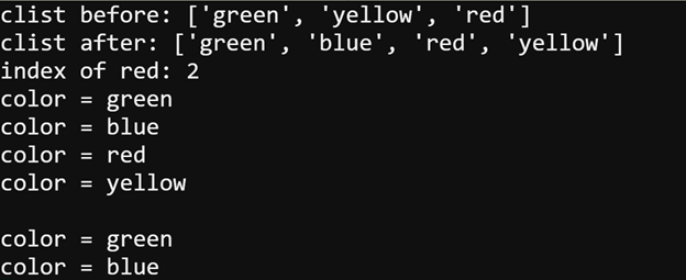
Yes, there is an easier way! A for color in clist: loop will automatically copy each successive item in clist into the color variable. If your script just needs to cycle through items in a list, this is the way to go!
Even though you have been working with lists of strings, lists can contain other data types, like int, and a microbit.pin object. Different types can even appear in the same list.
my_list = ['yellow', 1000, pin14]
Lists can be changed after they are created. In Python-speak, the term is mutable. Here are some ways to change lists in a script:
clist[1] = 'blue'         # replaces 'yellow' to 'blue'

clist.append('yellow')    # adds 'yellow' as the last item in the list

clist.index('red')        # finds the first instance of 'red' in the
                          # list and returns the index
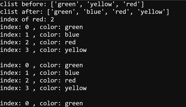
Your application can even use both list items and their index values in a list; here is an example that uses a for loop. Note how it uses len(clist) instead of 3. The len(clist) call returns the length of the list. It is currently 3, but if you added items to the list, the result of a call to len(clist)would automatically increase.
   for index in range(len(clist)):
        color = clist[index]
        print('index:', index, ', color:', color)
        sleep(1000)
    print()
Here is another example that uses enumerate instead of in range. Enumerate returns 2 values (a tuple) that contains the index number in the list and the item. In this example, the index number gets copied to the variable named index, and the color string (’green’, ’yellow’, or ’red’) gets copied to the variable named color.
       for index, color in enumerate(clist):
        print('index:', index, ', color:', color)
        sleep(1000)
    print()
Here is the script from the Try This section on the previous page with statements from the Did You Know section above added. It replaces ’yellow’ with ’blue’, adds ’yellow’ after ’red’, and gets the index of ’red’.
In this activity, you used lists to display different sequences of color names in the serial terminal.
There’s an easy way and a hard way to cycle through items in a list. Using the variable city and the list name c, write the code for a 4-item list of cities with a while True loop that will print them the ‘easy’ way.
Solution:
clist = [‘city1’, ‘city2’, ‘city3’, ‘city4’]

while True:
    for city in clist:
        print(‘city = ’, city)
        sleep(1000)
    print()
In Add a Light you built a second LED and wrote scripts to control both of them. In Intro to Lists, you got to see how to create and access lists. In this activity, you will add a third LED, and then use lists to set up custom LED on/off sequences. You will even use a list of LED pins and a list of on times in the same for loop to fully customize the light sequence.
(1) Setup from Add a Light
(1) LED – Red
(1) Resistor – 220 Ω (red-red-brown-gold)
(1) Jumper wire (black)
This script will blink the LEDs in sequence according to a list named pin_list.
# led_blink_list

from microbit import *

pin_list = [pin13, pin14, pin15]

while True:
    for pin in pin_list:
        pin.write_digital(1)
        sleep(500)
        pin.write_digital(0)
Instead of string objects like ’green’, ’yellow’, and ’red’, the list in this example contains microbit.pin objects: pin13, pin14, and pin15.
pin_list = [pin13, pin14, pin15]

while True:
The first time through the for pin in pin_list loop, pin gets set to pin13. So, in the first pass, pin.write_digital(1) is really pin13.write_digital(1), which turns the P13 light on. Likewise, pin.write_digital(0) is really pin13.write_digital(0), which turns the P13 light off.
    for pin in pin_list:
        pin.write_digital(1)
        sleep(500)
        pin.write_digital(0)
The second time through the loop, pin is pin14, so pin.write_digital(1) is really pin14.write_digital(1), and pin.write_digital(0) is really pin14.write_digital(0). The third time through the loop, pin is pin15. So, pin.write_digital(1) and pin.write_digital(0) are really pin15.write_digital(1) and pin15.write_digital(0).
Sometimes a little change can make a big difference in the way something behaves. For example, adding just one pin to the list will make the sequence look like the lights bounce back and forth between red and green.

Sometimes, a Python script needs a loop to access each successive item in more than one list. For example, maybe each color has a corresponding on-time in a different list. When used in place of in range(), Python’s zip() function makes this easy. Here’s an example:
# lists_with_zip
from microbit import *
color_list = ['green', 'yellow', 'red']
time_list = [ 1000, 200, 500]
for color, time in zip(color_list, time_list):
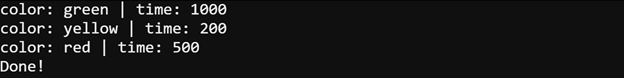
print('color:', color, '| time:', time)
print('Done!')
The first time through the loop, the color variable stores ’green’, while the time variable stores 1000. The second time through, color is ’yellow’, and time is 200. The third time through, color is ’red’ and time is 500. Each time through the loop, print(’color:’, color, ’| time:’, time) displays both variables.
Now that you’ve seen how to use a single loop with the zip() function to access related items in more than one list, let’s try it with custom LED on-times.
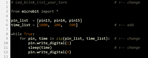
Create a script that turns the green on constantly for 10s, then flashes the yellow, and then finally ends with a solid red.
Solution.
name_list = [Emmanuel, Izzie, Inez, Jon]
score_list = [456, 435, 482, 421]
for name, score in zip(name_list, score_list):
Solution:
from microbit import*

while True:

pin13.write_digital(1)
        sleep(10000)
        pin13.write_digital(0)

        for n in range(0, 10):

            pin14.write_digital(1)
sleep(200)
        pin14.write_digital(0)
        sleep(200)

        pin15.write_digital(1)
In this activity, you will send very slow on/off signals to the P13 LED light circuit and measure the voltage that the I/O pin supplies to turn the light on and off. By slowing down the highs and lows, you will be able to measure the voltages the P13 pin supplies to the green LED.
Setup from Blink Sequencing.
(2) Alligator clip probes connected for voltmeter functionality, like in the Parts and Circuit from First Electrical Connections with a Breadboard
(1) 1 kΩ resistor (for the Your Turn section).
IMPORTANT: Your LED on voltage measurements might be considerably higher than the 2.65 V measurements shown below. Basically, if you get anything in the 2.5 to 3.3 V range, assume it’s good.
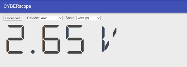
Earlier, we learned that the micro:bit’s microcontroller connects a pin like P13 to its 3.3 V supply in response to pin13.write_digital(1) and to its 0 V (GND) supply in response to pin13.write_digital(0). It looks like the 0 V (GND) signal checks out, but why does it only supply 2.65 V to turn the LED light on?
The answer is that the transistors inside the micro:bit that make connection between an I/O pin and 3.3 V have some internal resistance. With current for the LED circuit flowing through that internal resistance, the result is a voltage drop of 0.55 V inside the micro:bit, leaving 2.65 V for the LED circuit. This I/O pin behavior is called voltage drop under load. Again, your measurements could vary, and the variations will depend on temperature, version of micro:bit, and even microcontroller manufacturing variations from one batch to the next.
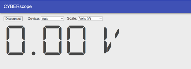
This script started as led_blink from Connect and Blink a Light. Aside from the fact that the green light was moved from P14 to P13, the led_blink_with_voltmeter script has two main differences. First, it has from multimeter import *, which has functions for measuring voltage and displaying it with the CYBERscope. Second, it measures voltage with voltmeter(device=”CYBERscope”) after each pin13.write call. This function call measures the voltage between the P2 and P0 alligator clips and sends the measurement data to the CYBERscope to be displayed.
# led_blink_with_voltmeter

from microbit import *
from multimeter import *                  # <-- added

while True:
    pin13.write_digital(1)
    voltmeter(device="CYBERscope")        # <-- added
    sleep(2500)
    pin13.write_digital(0)
    voltmeter(device="CYBERscope")        # <-- added
    sleep(2500)
Here, you will test I/O pin voltage without any load. You will do this by disconnecting the circuit “load” from the I/O pin “supply.”
In the main activity, you measured the I/O pin high voltage under load.
In the Try This section, you measured the I/O pin high voltage with no load.
In both activities the I/O pin low voltage was not under load because it was trying to supply 0 V to a circuit that had 0 V (GND) at the other end. No electrical pressure was applied, so no current was flowing through the circuit. Thus, no current “load” on the I/O pin.
What I/O pin voltage under load did you observe? What is your explanation?
In this activity, you used a voltmeter to measure the voltage supplied by the I/O pins to turn the LED on and off in the P13 LED light circuit.
Use the voltmeter to check the voltage across the yellow LED circuit. Confirm that it is similar to that of the green LED circuit.
Self-check
Solution: Make sure to change the pin in the script to 14. The reading should be approximately 2.95 V.
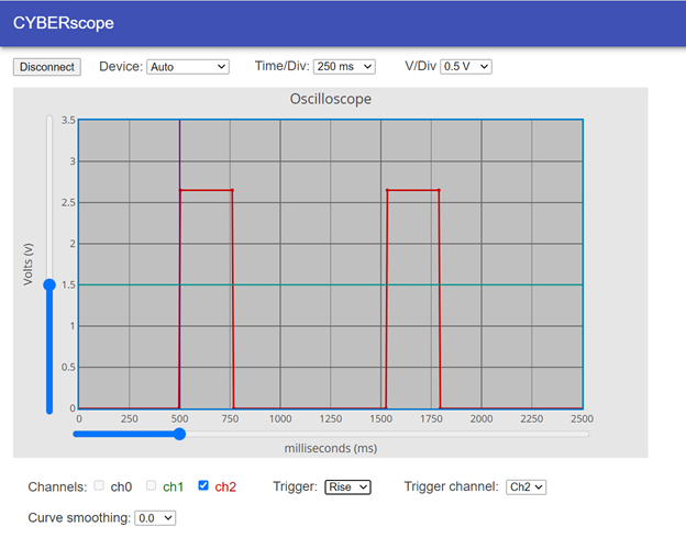
An oscilloscope is an instrument that graphs voltages over time. Engineers and technicians use them to check voltage signals, especially ones that repeat too rapidly to measure with a simple voltmeter.
In this activity, you will:
Same as Measure a Blinking Light with a Voltmeter (shown again below.)
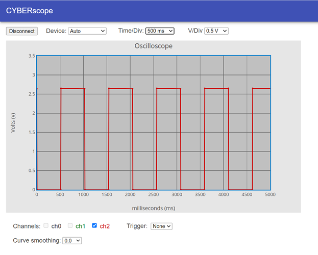
An oscilloscope plot graphs voltage over time. Since your script turns the light on for 500 ms, then off for 500 ms, the plot shows the voltage repeatedly stays at 2.65 V for about half a second and then at 0 V for half a second.
As you can see the script timing is not precise. It spends more than more than 500 ms high and low. The reason for this is because it takes the micro:bit time to execute each statement, and it also takes time for it to send that data to the CYBERscope.
When you adjusted the Time/Div from 1000 ms to 500 ms, you changed the x-axis increments from 1000 ms to 500 ms. The total amount of time it graphed dropped from 10,000 ms to 5000 ms.
This script also started as led_blink from Connect and Blink a Light. Again, the multimeter module is imported for sending data to the CYBERscope. The plot data is sent to the CYBERscope with plot(volts(pin2),”y2″). The plot function sends data to the CYBERscope formatted so that it can be plotted in the oscilloscope display. The value it sends is volts(pin2), which measures the voltage with the P2 pin (through the red alligator clip lead). The “y2” text string is forwarded to the CYBERscope, which results in the data being plotted on its red channel 2 (ch2) trace.
# led_blink_with_plot                     # <-- changed

from microbit import *
from multimeter import *                  # <-- added

while True:

    pin13.write_digital(1)
    sleep(1)                              # <-- added
    plot(volts(pin2), "y2")               # <-- added
    sleep(499)                            # <-- changed
    plot(volts(pin2), "y2")               # <-- added

    pin13.write_digital(0)
    sleep(1)                              # <-- added
    plot(volts(pin2), "y2")               # <-- added
    sleep(499)                            # <-- changed
    plot(volts(pin2), "y2")
The measurements have to be plotted before and after each pin13.write_digital call. Normal oscilloscopes send many data points; whereas, this script sends just the points before and after each signal level change. The sleep(1) is added between each pin13.write_digital call to give the voltage enough time to rise to its final value.
If you are curious why the sleep wasn’t needed for the voltmeter but is needed here, it’s because voltmeter() measurements are actually the average of ten measurements, taken every 10 ms. In contrast volts() is a single measurement.
In the main activity, you experimented with a 50% duty cycle signal. The high and low times were equal, and the plot showed that. Here, you will change it to a 25% duty cycle and observe the differences in the CYBERscope.
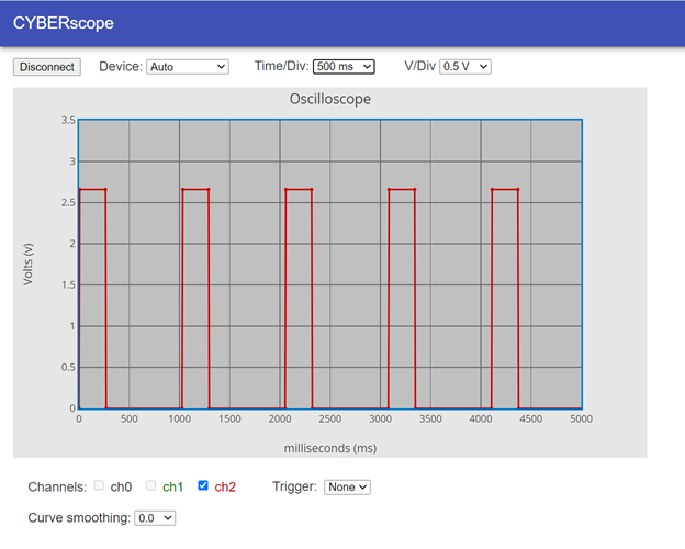
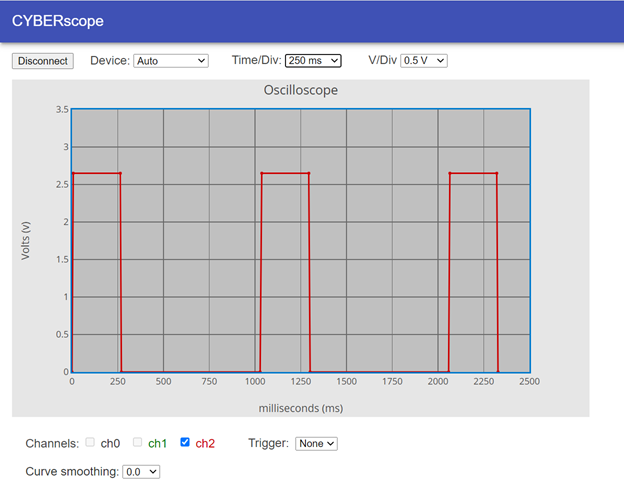
Oscilloscopes have a trigger feature that allows you to position the entire plot on the screen relative to a certain trigger time and trigger voltage. The trigger event can be rising or falling. If the trigger event is rising, it means that the voltage rose above the trigger voltage. Falling means the voltage fell below the trigger voltage. The oscilloscope takes the entire plot and aligns that rise or fall event with the vertical trigger time.
When binary on/off signals are plotted, they are described as having rising and falling edges. The rising edges are the lines that connect 0 V to 2.65 V, and the falling edges are the ones that connect 2.65 V to 0 V.
Change the resistor in the green LED circuit to a 1 kΩ resistor (brown-black-red-gold). What changes do you observe in the graph? (Make sure to switch the resistor back.)
Solution. Remember the Your Turn activity in Measure Blinking Light with a Voltmeter. Your measurements showed decreased voltage. The oscilloscope graph will show the same thing. More resistance resulted in less current. It turns out that the voltage will remain about the same. The increase in resistance results in less current, which in turn results in less light. The LED has (mostly) unchanging forward voltage, so the change in current is simply caused by more resistance. The voltage drops remain about the same, but since there is more resistance, there is less current to get the same voltage across the resistor.