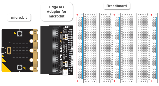
Parts
- micro:bit module
- Edge I/O Adapter for micro:bit (Rev B or higher)
- Breadboard
Gather the parts and place them in a row as shown in the picture.
Circuit
- Connect your micro:bit to the breadboard with the Edge I/O Adapter, following the animation and the checkmark instructions below it.
- Optionally, view the full-size clip microbit-edge-breadboard-setup.mp4 to play and pause between steps.
. 
- Make sure the breadboard is right-side-up so that its 1, 2, 3 row labels are at the top. The 28, 29, and 30 row labels should also be at the bottom.
- Set the Edge I/O Adapter on the left side of the breadboard so that:
- the adapter pin labeled P0 goes in the (a, 30) breadboard socket
- the adapter pin labeled 3V pin goes in the (a, 11) socket
- the two adapter pins labeled (+) go in the bus strip (+) column sockets next to the red line
- The two adapter pins labeled (-) go in the bus strip (-) sockets next blue line
- When you are sure the pins are started in the correct sockets, press down firmly on the edge adapter. The pins should sink all the way into the breadboard -by about ¼ inch.