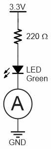
Current, the flow of electrons in a circuit, is measured in amps or amperes. In this activity, you will use an ammeter to measure current through a circuit. The trick to measuring current is that the ammeter needs to be connected in series with the circuit. That way, the same current that flows through the circuit flows through the ammeter to be measured. The circle with the A inside is the schematic symbol for ammeter.
In this activity, you will:
- Learn how current can be measured with an ammeter
- Learn how currents from more than one circuit connected to the same node have to add up according to Kirchhoff's current law.
Ammeter Parts
This activity re-uses the setup and LED Circuit parts from Measure Resistance, as well as parts for a second LED circuit and additional resistors for testing.
(2) green LEDs
(2) 220 Ω resistors (red-red-brown-gold)
(2) Jumper wires, black
(1) 1 kΩ resistor brown-black-red-gold
(1) 2 kΩ resistor red-black-red-gold
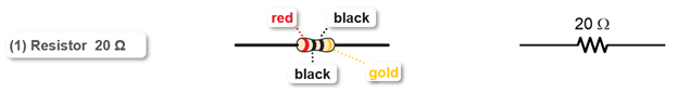
(1) 20 Ω resistor (red-black-black)
The 20 Ω resistor is part of the ammeter. It is important to use the correct one, so look carefully at the color bands so you don't mix them up! The color code for the 20 Ω resistor is red-black-black-gold:
Ammeter Circuit
Rcall that the circuit and procedure for measuring resistance with an ohmmeter was different from measuring voltage with a voltmeter. Measuring current with an ammeter also requires its own circuit and procedure different from the other two.
To start, you will need one LED circuit an the ammeter circuit on your board.
- Disconnect the USB cable from the micro:bit.
- Re-build the green LED circuit, if it is not already there from the previous activity.
- Use the animation and the instructions below it to connect continuity probes to your breadboard.
- Optionally, view the full-size measure-current-circuit.mp4 clip to play and pause it between steps.
- Plug the 20 Ω resistor into sockets (b, 30) and (b, 28) on the left terminal strip.
- Double check your connections! The resistor’s leads should be plugged into the same row as the Edge I/O adapter’s P0 and P2 pins (and the 3-pin headers).
- Connect alligator clips to the P0 and P2 3-pin headers, just like the voltmeter.
For the current measurement, you have to insert the 20 Ω resistor into the circuit. To do this:
- Unplug the ground wire from (j, 16) on the right terminal strip, and plug it into (j, 18).
- Connect the black probe to (i, 18) and the red probe to (h, 16).
- Now, instead of flowing from the LED’s cathode to GND, it flows from the LED’s cathode, through the 20 Ω resistor, and then to GND.
- Reconnect USB to the micro:bit and verify that the green light comes back on.
IMPORTANT: Remove the 20 Ω resistor after you are done with current measurements in this activity. It is only needed when measuring current, and it could cause errors in voltage measurements later if it’s not removed.