Measure Resistance with an Ohmmeter
An ohmmeter is a device that measures resistance. The basic unit of resistance is the ohm, and it’s abbreviated with the uppercase Greek letter omega (Ω).
This activity will guide you through:
- Building a simple micro:bit powered ohmmeter.
- Using the ohmmeter to measure the resistors you experimented with in the Build the LED Circuit activity.
- Practicing an important resistance measurement rule: Individual resistors need to be removed from the circuit to be measured.
- Calculating the equivalent resistance of:
- Two or more resistors connected end-to-end (in series).
- Two or more resistors connected side-by-side (in parallel).
A test circuit cannot have power applied to while measuring resistance. This second, important rule normally applies when using a repair manual, which might direct you to measure the resistance in a much larger circuit that’s part of some device. The device’s power would have to be turned off for an ohmmeter to take a valid measurement.
Circuits
In this activity you will have an ohmmeter circuit and an LED circuit. You will use the ohmmeter circuit to measure different resistors used in the LED circuit.
LED Circuit
Let's once again re-use the setup from First Breadboard Circuit — Build the LED Circuit.
The LED circuit may still be on your board. If not, re-build it now.
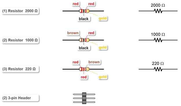
Ohmmeter Parts
You will also need the following additional parts, along with some jumper wires:
Ohmmeter Circuit
This ohmmeter circuit can measure resistances in the 100 to 10,000 Ω range.
- Use the animation and the instructions below it to create the ohmmeter circuit.
- Optionally, view the full-size measure-resistance-meter-circuit.mp4 clip to play and pause it between steps.
- Plug one 3-pin header into row 29, columns g, h, i.
- Plug the other 3-pin header into the lowest sockets in the center bus strip’s red (+) column.
- Plug a 2000 Ω resistor’s leads into (j, 29) and one of the center bus strip’s blue (-) sockets.
- Use a jumper wire to connect (f, 29) to (e, 29).
- Bend the resistor and jumper wire you just connected to make them sit flat against the breadboard.
- Connect the ends of your alligator clip probes to these 3-pin headers:
- Black to the 3-pin header in (g,h,i, 29)
- Red to the alligator clip in the 3-pin header in the bus strip’s red (+) column.
- Connect the other ends of the alligator clip probes to these sockets on the right terminal strip:
- Black probe to (j, 21).
- Red probe to (a, 21).