Physical Layout Considerations on the ActivityBot Chassis
The QTI Line Follower Kit for the Small Robot (it is compatible with all small Parallax robots) has clear assembly instructions. Please follow these instructions to set up your QTIs. The ColorPal placement should be in front of the QTI Line Follower sensors, close to the surface where the color samples will be detected. The WS2812 and piezospeaker could be wired on the breadboard in several different places but should follow the recommended schematic.
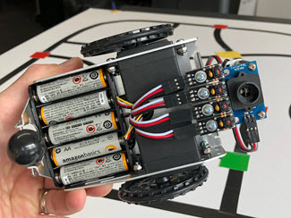
Some of the issues you’ll encounter in assembling this project are limited breadboard space, having a robust physical layout that doesn’t fall apart when retrieved from the table, sharing of power and ground connections to eliminate extra wires, etc. The placement of the ColorPal sensor will require you to devise a mount of some kind using whatever you have available (cardboard, Lego pieces, hot glue, etc.). Your workmanship is important here - take your time and build it in a way you can see the pieces, make adjustments to the setup and ultimately be proud of your work!
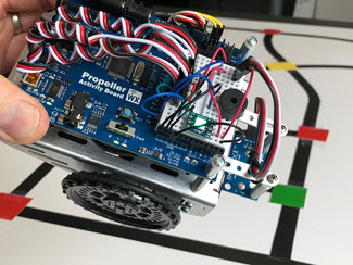
Two pictures provided below show how the components were arranged in this project. At the end of this page you will find wiring diagrams/schematics to connect your various components.
Electrical Tape Layout
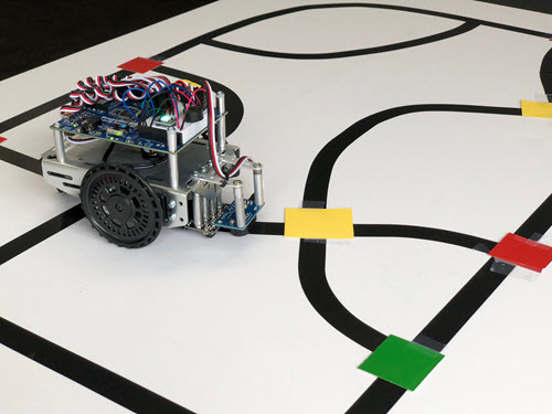
This electrical tape layout was made on a 24” x 36” foam-core poster board from big box office supply stores. You could also use a lighter-colored table or floor. Electrical tape is a very pliable material and can be formed to make corners. Keep the tape flat against the surface of the poster board and use scissors to cut it to avoid it coming loose (don’t stretch it apart and expect it to lay flat afterwards).
This project uses “dead reckoning” to make 90- or 180-degree turns so it’s using right-angle intersections and crossroads. Add a few inches of straightaways before the junctions to make it easy for the ActivityBot 360 to align and find its way back to the directed path of travel.
Schematics for Assembly
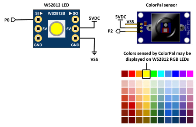
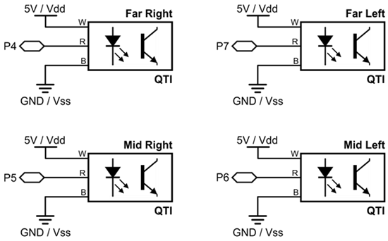
Refer to the ActivityBot 360 Electrical connections for the servo motors and piezospeaker circuit. The QTI Line Follower, WS2812 LED and ColorPal sensor schematics are below.
QTI
RGB LED/ColorPal