Gather the Parts
For this construction step, you will need:
- Assembled robot
- (2) 20 k-ohm resistors (red-black-orange) ONLY if your robot has the external encoders.
- (5) 1.5 V AA batteries - don't put them in yet!
- Needle-nose pliers - optional, but helpful
- Masking tape
- Pen
Make sure to use (5) 1.5 V AA batteries!
The ActivityBot's High-Speed Continuous Rotation Servos or Feedback 360° servos need 6 to 8 volts. Its five cell holder is designed for five alkaline cells because 5 x 1.5 V = 7.5 V. It's true that new and unused 1.5 V alkaline batteries can at times have a small amount of excess voltage. Therefore, five of these batteries can add up to 8.2 V, however, exceeding by only 0.2 V will not harm the servos in any way.
The output of an alternate DC (direct current) voltage supply should be measured to make sure it has the correct supply range before using it to avoid potentially damaging the servos.
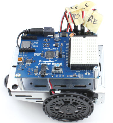
Label the Cables
- Put a masking tape label on the end of each encoder cable and servo cable, near the 3-pin socket.
- Trace each cable back to its origin to see where it is connected.
- Label each cable Right or Left, Encoder or Servo.
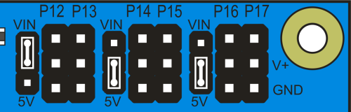
Prepare the Servo Ports
Each pair of 3-pin servo ports along the top of the Propeller Activity Board (original or WX version) has a shunt jumper on power-select pins to its immediate left.
Important! Make sure there is no USB cable or battery pack cable plugged into the board - moving jumpers with power connected could damage your board.
- Unplug the USB cable and battery pack if you have either of them plugged into the board.
- Move the shunt jumpers into the configuration shown below. Tip: If your jumpers do not have a little tab on them, needle-nose pliers will help.
- P12 & P13: VIN
P14 & P15: 5V
P16 & P17, 5V
Missing a Voltage Selection Jumper? Replacements are available - contact our sales department to order part #452-00043; there are three per board.
Plug In the Cables
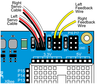
The servos and the external encoders have 3-wire cables: white = signal, red = power, black = ground. When plugging these cables into servo headers, be sure to align white wires with the P12 & P13 labels along the edge of the PCB, and the black wires along the row labeled GND (see the picture below).
The Feedback 360° servo also has a single yellow encoder feedback signal wire, which plugs into a separate servo header's I/O pin.
- Plug the servo's white-red-black cables into these servo ports
P12: Left Servo
P13: Right Servo - Plug the encoders into these servo ports, making sure the white or yellow signal line connects to the port's I/O pin, right by the P14 & P15 labels near the edge of the PCB.
P14: Left Encoder
P15: Right Encoder - ONLY IF YOU ARE USING EXTERNAL ENCODERS, use 20 k-ohm resistors to connect the P14 and P15 sockets to the left of the white breadboard to the 3.3 V power sockets just above the breadboard.
With external encoders (left/top); with Feedback 360° servos (right/bottom)
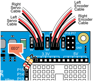
*You only need P14/P15 resistors (shown on the left) for ActivityBot kits using External Encoders (#32500).
Double-check your Connections
For all robots
- P12 & P13 servo port shunt jumper — Set to VIN.
- P14 & P15: servo port shunt jumper — Set to 5V.
- Left servo cable — P12 servo port.
- Right servo cable — P13 servo port.
- Left encoder cable — P14 servo port.
- Right encoder cable — P15 servo port.
- All encoder cables — White or yellow signal line goes to the port's I/O pin, closest to the edge of the board.
For ActivtyBots with External Encoders
- Left encoder cable — the other end is plugged firmly into the encoder sensor.
- Right encoder cable — the other end is plugged firmly into the encoder sensor.
- P14 socket — connected to a 3.3V header with a 20 k-ohm resistor (red-black-orange).
- P15 socket — connected to a 3.3V header with a 20 k-ohm resistor (red-black-orange).
- Both 20 k-ohm resistors — if you trimmed them, make sure the leads are still long enough to sit all the way down in the socket for a good electrical connection.
Insert the Batteries
- Place (5) 1.5 V AA batteries into the battery pack.
- Plug the battery pack's barrel plug into the Propeller Activity Board's (original or WX version) barrel jack.
Congratulations, construction is complete!
- Keep following the links below to set up your software and start programming.