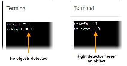
The test code displays the state of each IR detector: 1 = no infrared reflection detected, 0 = yes, infrared reflected from an object is detected.
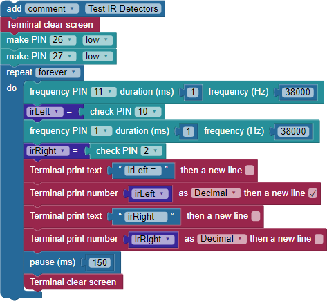
Test Code
- Log into your BlocklyProp account and create a new project named Test IR Detectors.
- Build the project shown below, and save it.
- Click the Run Once button.
- Point your ActivityBot so that both IR detectors are pointing away from any objects, and verify that both detectors report 1.
- Place your hand in front of (and facing) the right IR detector, about 10 cm (≈ 4 in) away. This should display irLeft = 1 and irRight = 0, as shown below.
- Repeat for the left IR detector and verify that the display updates to irLeft = 0 and irRight = 1.
- Repeat for both, and verify that both display 0.
- If all the tests worked, you are ready to continue to the next section. If not, go through the Troubleshooting list below.
Troubleshooting
It is essential to make sure that both IR detectors work correctly before continuing.
- If your IR output is stuck at 1 or 0, it usually indicates a wiring problem. In this case, go back and check your wiring.
- If the IR flickers to zero when it shouldn’t (because there are no objects in range) try turning off any nearby fluorescent lights, and retest.
- If the IR only sporadically detects when an object is right in front of it, check the color codes on the resistors connected to P11 and P1. They should be brown-black-red for 1 kΩ. Also, make sure your ActivityBot is not in direct sunlight.
- Make sure both IR sensors are working well before continuing to the next activity.
What the IR Sensors Can't See
Remember, the IR sensor system is looking for reflected infrared light. Shiny, light-colored objects reflect infrared light well, while dull, dark-colored objects absorb infrared light instead of reflecting it. So, if your IR sensors can't see your black shoes or a black plastic wastebasket, don't worry, that is normal.
How it Works
First, the program makes I/O pins P26 and P27 output low (0 V). Not only does this turn off the P26 and P27 LEDs, but it also connects the D/A0 and D/A1 sockets to 0 V. The IR LED cathodes are connected to these sockets, using them for a ground connection. (We will explain why in a later activity.)
The rest of the code is inside a repeat forever loop. First, a frequency out block generates a 38000 Hz signal on P11, for 1 millisecond. P11 connects to an IR LED, causing it to strobe on/off very rapidly in a 1 ms burst.
This block is followed immediately by a check PIN block, which stores the input state of P10 in a variable named irLeft. P10 connects to the left IR receiver circuit. These IR receivers detect not just the presence of infrared light but are most sensitive to IR light that is strobing on/off very rapidly, at 38 kHz (38000 Hz). The IR detector sends a low signal (0 V) when a reflected 38 kHz IR signal is detected, and a high signal when no such signal is detected.
The process is duplicated for the right-side IR circuitry with another frequency PIN + check PIN block pair, storing the IR receiver's output in the irRight variable.
The next six lines should look familiar by now. The four Terminal print blocks display labels and values for the irLeft and irRight variables. A pause (ms) 150 block slows down the loop for optimal display. Finally, a Terminal clear screen block erases the old data before the next trip through the loop.
Did You Know?
Infrared — It means “below red,” and it refers to the fact that the light’s frequency is below that of red on the color spectrum.
Filtering — The IR receiver has a filter built in that makes it look for infrared that flashes on/off 38000 times per second (38 kHz). This allows it to differentiate between infrared coming from the TV remote and other IR sources such as halogen and incandescent lamps as well as sunlight streaming in through a nearby window.
Sunlight — Even though the IR receiver filters for sunlight, direct sunlight can often swamp the IR LED’s signal. Try to keep it indoors and out of any sunlight streaming in through windows.
Try This
The P26 and P27 lines are currently in use providing 0 V to the IR LED cathodes, so you cannot use their LEDs for indicating the IR detector states like you did with whiskers. So, let’s build some LEDs on the breadboard for "object detected" indicators.
- Collect two red LEDs, two 220 Ω resistors (red-red-brown), and two black jumper wires from your kit.
- Use those parts to build the two added LED indicator circuits shown here.
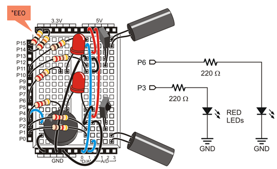
*P14/P15 resistors are only needed for ActivityBot kits using External Encoders (#32500).
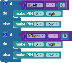
Next, you will need to modify the code to turn a given light on if its IR receiver returns 0, or off if it returns 1.
- Use the Save Project As button to make a copy of your project with a new name, such as Test IR Detectors Try This.
- Add the two if...else blocks shown below to the repeat forever loop, just before the pause (ms) block.
- Run the program and verify that each red LED turns on when you put an obstacle in front of the IR object detector that’s next to it.
Your Turn - Test for IR Interference
If you have an infrared remote, you can further modify your IR detection code so that it sounds an alarm if it detects IR interference from the environment. This is a useful test to find out if nearby fluorescent lights or other devices are sending out signals that could affect your robot's behavior. The key is not to emit any infrared with the IR LEDs. If the receivers still send a low signal, there must be IR interference coming from another source.
If interference is detected, make the piezospeaker get your attention with a series of six 50 ms, 4 kHz chirps separated by six 50 ms pauses. You can use a TV remote to test this.
- Use the Save Project As button to make a new copy, and name it Test IR Detectors Your Turn.
- Point an infrared remote (such as a TV remote) at your IR receivers, and press and hold a button. Verify that the indicator lights come on.
- Add an if...do block that plays the series of six 50 ms, 4 kHz chirps separated by six 50 ms pauses if either irLeft or irRight hold a 0.
- Save the program to EEPROM.
Now you can disconnect the robot from the computer and walk around your workspace. Try pointing your robot at different light sources. If you hear the beeping alarm, you know that a 38 kHz infrared signal is detected. The ballast on some styles of fluorescent tube lighting is notorious for causing this kind of IR interference.