Testing Your cyber:bot QTIs
Test the QTI Sensors Using Micro:bit’s LEDs
You will be adding a second module to your micro:bit project for the QTI
Hardware Setup
- Set the cyber:bot board’s power (PWR) switch to Position 0.
- Make sure the battery holder is loaded with 5 AA batteries.
- Make sure the battery holder’s barrel plug is firmly plugged into the cyber:bot board’s barrel jack.
- Connect your micro:bit module to your computer with a USB cable.
Software Setup
- In a browser, go to makecode.microbit.org to open the micro:bit Block Editor.
- Add three modules to the project: cyberbot.py, qti.py, and intbits.py.
- Go to Add extensions to your micro:bit.
- Skip the Quick Start section, and instead start at the section titled Adding a Module to micro:bit Filesystem.
- Watch the video and then add the cyberbot.py module to the project by following the instructions from there to the end of the page.
- Next, follow the same steps to add the qti.py module to the project. It will be in the same folder with cyberbot.py.
- Repeat the steps one more time to add the qti.py module to the project. It will also be in the same folder with cyberbot.py.
Project: QTI_Display_Detections
- Set the name to QTI_Display_Detections, enter the project below.
(See Save & Edit Projects and Flash Projects with MakeCode Editor.) - Click Download.
(See Flash Projects with MakeCode Editor.)
- Set the cyber:bot board’s PWR switch to position 2.
- Position your robot over the black line on your track. The QTI sensors directly over the line will cause the corresponding column of micro:bit LEDs to illuminate.
- Move the robot around slightly to test each QTI sensor Place each QTI sensor over black and then white to verify that the LEDs turn on and off, as shown in the video below.
If the sensors don’t see the line, try the following adjustments:
- Double-check all of your wiring connections to make sure the sensors are properly connected to power, ground, and each I/O pin.
- Try replacing the jumper wire connecting to 5 V with a 220 ohm resistor. This makes the QTIs less bright, which might be overwhelming with a shiny line or shiny paper.
- Try removing the nylon spacers from one of the sensor’s posts. If this improves performance, remove it from the rest of the posts.
IMPORTANT: Do not continue until all four QTIs are working properly as shown above. This might take some troubleshooting of errors made while connecting the QTIs as well as some adjusting of the spacers. It will also be important that the 5×5 LED display jumps by one column when the black stripe is moved from one QTI to the next. If it instead skips back and forth, it might mean that the QTI cables are swapped -not plugged into the correct QTIs. Set the cyber:bot board’s PWR switch to 0 if you adjust the circuit.
- Set the PWR switch to 0 until you are ready to rerun this project, or until you are ready to run the next project.
How It Works – Display QTI States with LEDs
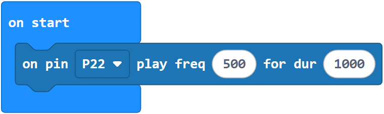
This statement copies line detection information for all four QTI sensors into a single int variable:

The qti read start (Pin7) end (Pin4) call returns the states of QTI sensors connected to sockets P7 through P4. These states are stored as binary 1 and 0 digits in the int variable named pattern. If a digit is 1, it indicates a black or non-reflective surface. If it’s 0, it indicates a white or reflective surface.
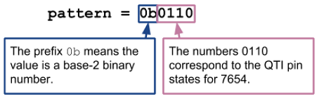
Suppose the two middle QTI sensors are over a black line so that they are both 1’s. The pattern variable’s value would be 0b0110.
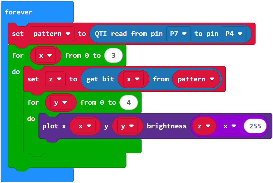
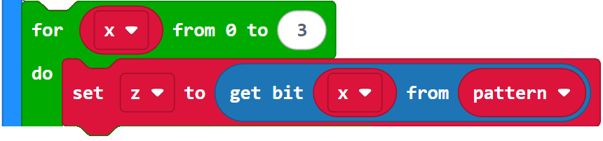
After storing the QTI states, a loop uses the qti module’s check_bit method to successively check binary digits in pattern and store them in the z variable. The for x in range(0, 4) loop starts at the rightmost binary digit in pattern and works its way left by increasing the x variable’s value with each repetition: 0, 1, 2, 3. As an argument in the check_bit method, x selects which binary digit in pattern to return, and that binary 1/0 return value gets stored in the z int variable.
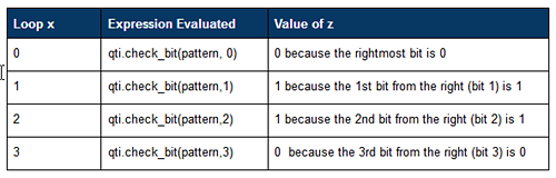
With the example 0b0110, this is how z evaluates at each loop repetition:
A nested loop turns all micro:bit LEDs in certain columns on or off to indicate which QTIs are over a black or white surface:
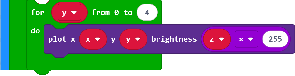
The third argument in plot x (x) y (y) brightness (z * 255) sets the brightness (from 0 to 9). If z is 0, then the brightness is z * 9 = 0 (off). If z is 1 then the brightness of z * 9 = 9 (max brightness). Instead of just one LED, the for y in range (0,5) loop makes plot set all LEDs in a given x column to on or off in response to a z value of 1 or 0. For more info on display, try the examples in the LED Matrix tutorial.