Parts
- (1) Connected micro:bit, edge, and breadboard from Connect the micro:bit to a Breadboard
- (1) USB cable
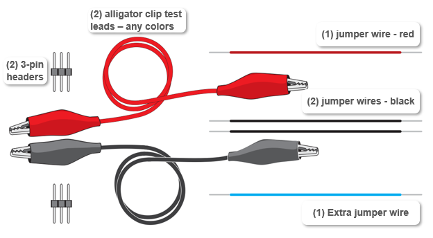
- (2) Alligator clip test leads
- (2) 3-pin headers
- (1) jumper wire - red
- (2) jumper wires - black
- (1) jumper wire - blue
- Gather the parts and get ready to build your micro:bit continuity tester!
Circuit
- Use the animation and the checkmark instructions below it to connect continuity probes to your breadboard.
- Optionally, view the full-size connect-continuity-probes-to-breadboard.mp4 clip and play and pause it between steps.
- On the left terminal strip:
- Plug the first 3-pin header into row 30, columns c, d, and e.
- Plug the second 3-pin header into row 28, columns c, d, and e.
- Check to make sure they are in the right sockets. Also, the lower 3-pin header should be in the same row as the edge adapter’s P0 pin, and the upper one in the same row with the edge adapter’s P2 pin.
- Grab a metal end of a black jumper wire with an alligator clip. (If the clip grabs the wire's vinyl coating, there is no electrical contact.)
- Grab the metal pins of the 3-pin header in row 30 with the alligator clip at the other end of the test lead you clipped to the black wire.
- Grab a metal end of a red jumper wire with another test lead’s alligator clip.
- Grab the 3-pin header in row 28 with the alligator clip at the other end of the test lead you clipped to the red wire.
- On the right terminal strip:
- Plug the black wire into (j, 17)
- Plug the red wire into (f, 16)
Keep the alligators apart! Adjust the plastic covers on the alligator clips when you connect them to the 3-pin headers, to make sure the two probes are not touching and making electrical contact.