In this activity, you will send very slow on/off signals to the P13 LED light circuit and measure the voltage that the I/O pin supplies to turn the light on and off. By slowing down the highs and lows, you will be able to measure the voltages the P13 pin supplies to the green LED.
Parts
Setup from Blink Sequencing.
(2) Alligator clip probes connected for voltmeter functionality, like in the Parts and Circuit from First Electrical Connections with a Breadboard
(1) 1 kΩ resistor (for the Your Turn section).
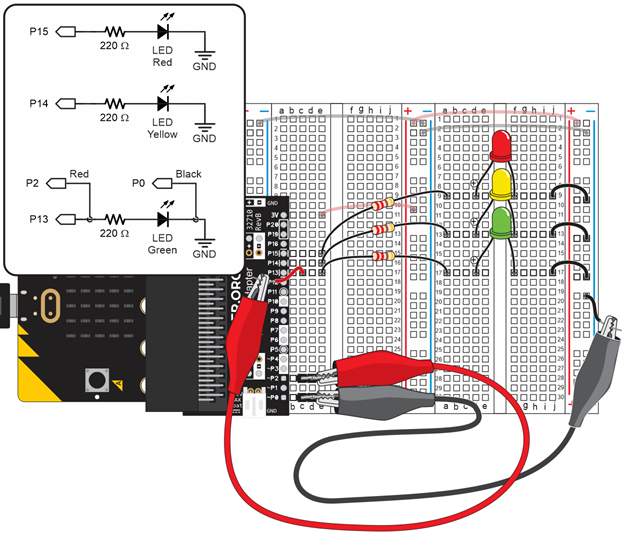
Circuit
- Connect the red P2 probe to P13. That would be b, c, or d in row 17.
- Connect the black P0 probe to the right bus strip’s (-) columns.
- IMPORTANT: Make sure that a 20 Ω resistor IS NOT plugged into the left terminal strip’s (b, 28) and (b, 30) sockets.