Let's start putting the S3's Hacker Port to use by connecting and controlling a Parallax Standard Servo. This tutorial will first demonstrate how to make a Standard Servo hold three different positions, and then how to approximate smooth, continuous motion with small, evenly-timed changes in position. With the S3’s Hacker Port, the physical connection is extremely easy and with BlocklyProp, coding is greatly simplified.
You will need the following accessory parts:
- (1) Parallax Standard Servo (#900-00005)
- (1) 3” Jumper Wire (#800-00016) or long twist-tie
A hobby servo is a small device that controls the position of flaps, rudders, and steering in many radio-controlled toy planes, boats, and cars. The Parallax Standard Servo is a hobby servo that can also be useful in many robotics and animatronics projects. Since it can both move to and hold a position, it is ideal for tasks like rotating a distance sensor or controlling the fingers in a robotic hand.
For more information on Standard Servos and how they work, see: Propeller C Simple Devices - Standard Servo.
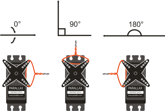
Servo Angle Marker
It helps to create some sort of angle marker on the turning part of the servo, the horn, to more easily indicate which position it is in. A jumper wire or twist-tie works well for this.
- Find the middle of the servo’s range by gently twisting the horn right and left to find the mechanical stops, then positioning it in the middle of its range.
- Twist the wire through the top two holes at the center of its range to mark the "middle" position. When finished, it will most likely look something like the figure below.

A Parallax Standard Servo is rated for a 4 to 6 V (volt) supply. The S3 User Guide notes that the S3 provides regulated 5V power, Ground (G) and access to I/O Pins 0 - 5 from the Hacker Port. Connections to 3.3 V power and Analog Pins 0 and 1 are also available from the Hacker Port.
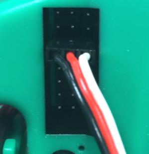
All the info you need to properly connect the servo to your S3 is in the image below. Remember that it is printed right on the surface of your S3 directly adjacent to the Hacker Port. As you can see, there are 8 rows of pins arranged in 3 columns.

Connect the Servo to the S3
Make sure the power is off on your S3 and it is unplugged from your programming/charging cable. Connect the Standard Servo's black/red/white cable connector to the pin row marked P0. Orient the connector so that the black wire is connected to the Ground column, the red wire is connected to the middle (5V), and the white signal connector is on the pin column - all along the row marked P0. Be careful not to accidently connect it to one of the rows labeled A0 or A1.
Holding Three Positions
Now, you can write the BlocklyProp Standard Servo test program to hold the three positions shown above. The code should move the servo to the three positions (0°, 90°, and 180° ) with three seconds to move between and hold each position. This code will also change the indicator LEDs based on the servo position. While the program is running, the servo will resist any attempt to move it out of position. When the program finishes, the servo will stop resisting.
- Point your browser to BlocklyProp, login, and begin a new project for the S3.
- Name your program Standard Servo Test.
In the ACTIONS > MOTORS category, you will find the rotate servo block and disable servo block. Other blocks will not be discussed, as they were used in previous tutorials.
- Snap the following program together with the settings shown.
- Save, compile, load to EEPROM, and run the program. Verify that the servo holds the 0° position, then the 90° position, and finally the 180° position each for about 3 seconds.
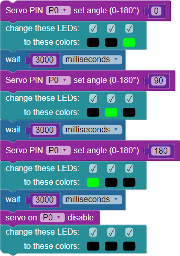
With BlocklyProp, the code explains itself:
- The drop-down menu in the rotate servo block allows you to set the pin (the image is set to 0, the default, because that is the row the servo is connected to).
- The number block allows input of an angle value in degrees. Click in the window to change this setting (0 to 180 when using a Standard Servo.
- The wait block allows you to set your wait time value to 3000 ms (3 seconds) between each move as intended. Finally, the disable servo block is added and set for the same pin # (P0). Note the indicator LED feedback at each position.
As the image above shows, the rotate servo block allows you to set two parameters: the pin the servo is connected to and the servo angle in degrees. For example, to make the servo connected to P0 turn to 90-degrees, the block is set to P0 and 90. Keep in mind that the rotate servo block does not wait for the servo to get into position - it is necessary to include a wait block for the servo to reach the desired position before setting a new angle. Finally, the disable servo block makes sure that pulses to the servo are ended.
Note: Standard Servos have a 180-degree range, plus or minus small differences between individual units. Be careful not to enter a servo angle greater than 180 degrees or you could damage the motor.
Your Turn
- Try modifying the program to make the servo hold a 45° angle and a 135° angle. Again, use LED feedback. Disable the servo. Verify it works as you would expect.
- Use a loop (x times) block to program the servo to move from 0° to 180° back and forth continuously with an appropriate delay between the moves - ten times - with LED feedback. Disable the servo at the end.
Special thanks to Parallax friend Whit Stodghill for his assistance in writing, editing, and testing material for these S3 tutorials.