Skip to content
Parallax Learn

Parallax Learn

  • Welcome
  • Tutorials
        • Tutorial Series head tag

          Tutorial Series
        • Tutorial Series

          The special, classroom-ready series pages are organized collections of tutorials for our most popular hardware and/or languages. The tutorials for each topic are conveniently accessible from a single page, shown in the order it is recommended that they be completed.
        • Robotics Series Head tag

          Robotics Series
        • Robotics Series

          • Artificial Intelligence
          • Cybersecurity: Radio Data tutorialCybersecurity
          • cyber:bot + Python
          • cyber:bot + MakeCode
          • Boe-Bot Tutorial SeriesBoe-Bot
          • Arduino Shield-Bot
          • ActivityBot with C TutorialsActivityBot + C
          • ActivityBot with BlocklyProp Tutorial SeriesActivityBot + BlocklyProp
          • Scribbler 3 Tutorial SeriesScribbler 3
        • Electronics & Programming Series Head tag

          Electronics & Programming Series
          • BS2 Board of Education Tutorial SeriesBS2 Board of Education
          • Propeller C-Language BasicsPropeller C Basics
          • FLiP Try-It Kit C Tutorial SeriesFLiP Try-It Kit + C
          • FLiP Try-It Kit BlocklyProp TutorialsFLiP Try-It Kit + BlocklyProp
          • Badge WX Tutorial SeriesBadge WX
          • Propeller BlocklyProp Basics and ProjectsPropeller BlocklyProp Basics
          • View All Tutorial Series »
        • Browse Tutorials
        • Browse Tutorials

          Individual tutorials sorted by robot or kit, and language.
        • By Robot or Kit
          • ActivityBot
          • SumoBot WX
          • Boe-Bot
          • Shield-Bot
          • cyber:bot
          • Badge WX
          • ELEV-8
          • ARLO
        • By Language
        • By Language

          • Propeller C
          • Arduino
          • BlocklyProp
          • PBASIC
          • Python
          • MakeCode
          • View All Tutorials »
  • Educators
  • Reference
  • Downloads
  • Home
  • All Courses

ELEV-8 v3 Quadcopter Assembly Guide

Curriculum

  • 1 Section
  • 40 Lessons
  • Lifetime
Expand all sectionsCollapse all sections
  • ELEV-8 v3 Quadcopter Assembly Guide
    40
    • 1.0
      Step 1: Do I Need to Loctite® the Set Screws?
    • 1.1
      Step 2: Attach Motors to Motor Mounts
    • 1.2
      Step 3: Feed Motor Wires Through Booms
    • 1.3
      Step 4: Bolt Motor Mount and Landing Gear to Booms
    • 1.4
      Step 5: Insert Tube Plugs
    • 1.5
      Step 6: Prepare the Top Chassis Plate
    • 1.6
      Step 7: Connect Booms to Top Chassis Plate
    • 1.7
      Step 8: Attach the Bottom Chassis Plate
    • 1.8
      Step 9: Attach Battery Straps and Foam Pads
    • 1.9
      Step 10: Connect the ESCs to the Motors
    • 1.10
      Step 11: Label ESC Signal Cables
    • 1.11
      Step 12: Route ESC Signal Cables through Chassis
    • 1.12
      Step 13: Bolt Standoffs to Isolation Plate
    • 1.13
      Step 14: Mount the Flight Controller and PDB
    • 1.14
      Step 15: Install the FC Power Cable
    • 1.15
      Step 16: Shield Sensors and Install FC Cover
    • 1.16
      Step 17: Attach the Isolation Assembly
    • 1.17
      Step 18: Connect the ESCs to the PDB and FC
    • 1.18
      Step 19: Connect and Mount Your Radio Receiver
    • 1.19
      Step 20: Connect PDB Power Cable and Secure Battery
    • 1.20
      Step 21: Configure the Transmitter and Bind to Receiver
    • 1.21
      Step 22: Install Software
    • 1.22
      Step 23: Install or Update Firmware
    • 1.23
      Step 24: Configure Flight Controller
    • 1.24
      Step 25: Calibrate the ESC Throttle Range
    • 1.25
      Step 26: Configure Motor Spin Direction
    • 1.26
      Step 27: Mount ESCs to Booms
    • 1.27
      Step 28: Full Systems Check
    • 1.28
      Step 29: Fasten Propeller Adapters
    • 1.29
      Step 30: Attach Propellers
    • 1.30
      Section 1: Assemble the Booms
    • 1.31
      Section 2: Assemble the Chassis
    • 1.32
      Section 3: Connect the ESCs
    • 1.33
      Section 4: Make the Isolation Assembly
    • 1.34
      Section 5: Install the Electronics
    • 1.35
      Section 6: Software and Firmware
    • 1.36
      Section 7: Configure the ESCs
    • 1.37
      Section 8: Final Testing
    • 1.38
      Step 19b: Spektrum AR610 and AR8000 Receivers
    • 1.39
      Step 19a: Spektrum SPMAR620 Receiver

Step 26: Configure Motor Spin Direction

Now you will check that the motors are spinning in the desired direction. If any motors are spinning in the wrong direction, it is a simple matter of switching any two of the ESC outputs to fix the issue.

Parts Needed:

  • ELEV-8 v3 Assembly w/ LiPo Battery
  • Computer with software & firmware installed from Step 22
  • USB A to Micro B cable

Instructions:

Warning! Propellers should not yet be installed on your ELEV-8 v3. If you have done so, remove them now before continuing.

  1. Connect your ELEV-8 Flight Controller to your computer’s USB port with a USB A to Micro B cable.
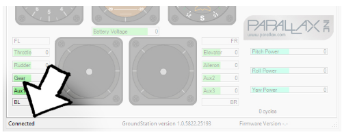
  2. Open the ELEV-8 GroundStation software.  The Status tab will be displayed first.  Use the information displayed in the bottom-left corner to verify that the ELEV-8 v3 is properly connected.  It will display “Connected” if it is

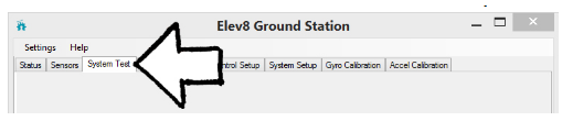
  1. Once the ELEV-8 v3 is connected to the GroundStation software, click on the System Test tab.

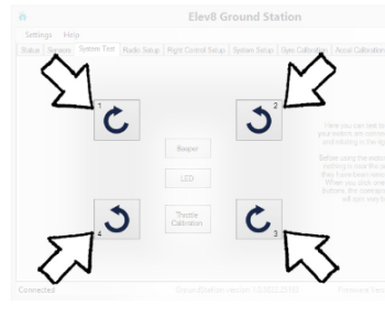
  1. Make sure the propellers are not mounted on the motors, and then use the buttons with circular arrows to verify that each motor spins in the correct direction. Click the “Buzzer” and “LED” buttons to make sure both the buzzer and LED are responding correctly as well.  The buzzer will do a two-tone beep and the LED will cycle through a rainbow of colors.

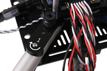
If the motor spun in the correct direction (as indicated by the markings on your top chassis plate, shown below), skip to step 8. If it did not, follow steps 5-7.

If the Motor Did Not Spin in the Correct Direction:

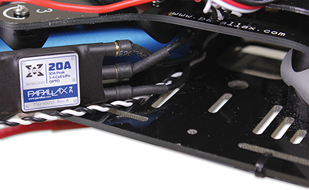
  1. Turn the ELEV-8 over and locate the ESC corresponding to (matching the number of) the motor in question.
  2. Locate any two of the (three) blue extension wires running to the ESC and unplug them from the ESC.

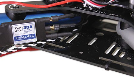
  1. ​Switch the extension wires for one another, and plug them back in. You have now reversed (corrected) the motor’s spin direction.

  1. Repeat instructions 1-8 as necessary for the three remaining motors/ESCs.

Printer-friendly version
Step 25: Calibrate the ESC Throttle Range
Prev
Step 27: Mount ESCs to Booms
Next

DISCUSSION FORUMS | PARALLAX INC. STORE

About | Terms of Use | Feedback: learn@parallax.com | Copyright©Parallax Inc. 2024

© 2026 Parallax Learn • Built with GeneratePress