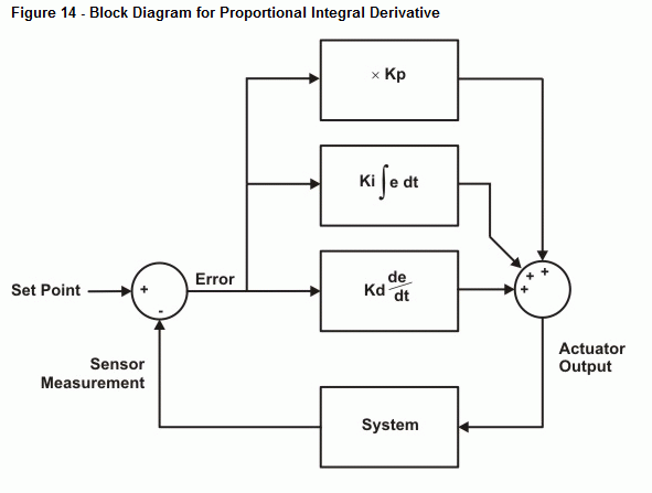
A PID control loop involves some contributions from each of the three kinds of control: proportional, integral, and derivative. The amount of contribution that each of the controls makes can be adjusted by changing their proportionality constants, Kp, Ki, and Kd. By making these constants larger or smaller, you can make the contribution of one of the controls more dominant or subtle in the system. One system might need only light integral control, some proportional and strong derivative, while another system might need strong integral and proportional controls, but not much derivative, while still another system might need roughly equal measures of each.
Here are several important things to keep in mind when working with PID control loops:
- Error is the difference between the level you want and the level that is measured, and control loops work to correct error.
- Proportional control resists error by applying an opposing influence that is proportional to the error.
- Integral control detects and corrects trends in error over time.
- Derivative control detects and resists abrupt changes in the system.

The next example program will perform this PID control loop. To make comparisons easier, Kp, Ki, and Kd are all set to 10.

Example Program - PidAlgorithm.bs2
Keep in mind that proportional always does some work when there's some error. However, integral and derivative are ready to do extra work to correct the error, integral to correct trends, and derivative to correct abrupt changes.
- Enter, save, and run PidAlgorithm.bs2.
- Here is a series of sensor inputs that the integral control will detect as a trend and resist much more strongly than either proportional or derivative: 1 2 3 4 5 5 5 5 5 5 5 5 5
- Here is a series of sensor measurements that derivative will work hard to correct while proportional and integral don't do nearly as much: 3 -3 4 -4 5 -5 6 -6 5 -5 4 -4
' PidAlgorithm.bs2
' Demonstrates how a combination of proportional, integral, and
' derivative control influence error correction in a feedback loop.

' {$STAMP BS2}
' {$PBASIC 2.5}

SetPoint       CON     0                     ' Set point
Kp             CON     10                    ' Proportionality constant
Ki             CON     10                    ' Integral constant
Kd             CON     10                    ' Derivative constant

Current        CON     0                     ' Array index - current error
Accumulator    CON     1                     ' Array index - accumulated error
Previous       CON     2                     ' Array index - previous error
Delta          CON     3                     ' Array index - change in error

sensorInput    VAR     Word                  ' Sensor input variable
error          VAR     Word(4)               ' Four different types of errors
p              VAR     Word                  ' Proportional term
i              VAR     Word                  ' Integral term
d              VAR     Word                  ' Derivative term
drive          VAR     Word                  ' Output

DO

  DEBUG "Enter sensor input value: "
  DEBUGIN SDEC sensorInput

  ' Calculate error.
  error(Current) = SetPoint - sensorInput

  ' Calculate proportional term.
  p = Kp * error(current)

  ' Calculate integral term.
  error(Accumulator) = error(Accumulator) + error(Current)
  i = Ki * error(Accumulator)

  ' Calculate derivative term.
  error(Delta) = error(Current) - error(Previous)
  d = Kd * error(delta)

  ' Calculate output.
  drive = p + i + d

  ' Display values.
  DEBUG CR, CR, "ERROR", CR,
        SDEC ? SetPoint, SDEC ? sensorInput, SDEC ? error(Current), CR,
        "PROPORTIONAL", CR,
        SDEC ? Kp, SDEC ? error(Current), SDEC ? p, CR,
        "INTEGRAL", CR,
        SDEC ? Ki, SDEC ? error(accumulator), SDEC ? i, CR,
        "DERIVATIVE", CR,
        SDEC ? Kd, SDEC ? error(Delta), SDEC ? d, CR,
        "OUTPUT", CR,
        SDEC ? p, SDEC ? i, SDEC ? d, SDEC ? drive, CR, CR

  ' Save current error to previous error before next iteration.
  error(Previous) = error(Current)

LOOP
Your Turn - Tuning the PID Control Loop
Assume that your sensor inputs will range from -10 to 10. Adjust your constants (Kp, Ki, and Kd) so that the maximum contribution any of the controls can make to the output ranges from 650 to 850. To get the integral control to adhere to this requirement, you will also have to use the MIN and MAX operators.
