PID Control with the BASIC Stamp
Most of us tend to enjoy the benefits of control systems without ever giving them a second thought. Consider the heaters, coolers, and thermostats that maintain the comfortable temperatures in our homes and workplaces. We just set the temperature on the thermostat, and the control system takes care of the rest. In this case, the control system's job is to regulate temperature, and when it does it's job we hardly think about it at all. Now, if it stops working during a heat wave or cold snap, well, that's an entirely different story.
More examples of control systems can be found inside our cars, where they are responsible for the smooth ride, anti-lock braking, fuel delivery, and ignition, just to name a few. Factories make use of control systems to maintain fluid levels in tanks, temperatures in curing ovens, and automated placement of parts in assembly lines. In the robotics world, control systems are used to help them maintain balance, distance from other robots or walls, and to refine navigation. With so many projects and products using control systems, the design techniques for control systems can be a useful addition to just about any inventor's toolbox.
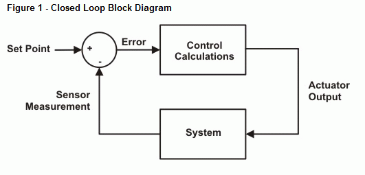
Closed loop control is the kind of control where information from sensors is used to determine what the actuators in the system do. It is so named because the diagrams that describe the interaction between sensors and actuators draws a closed loop. (See Figure 1.) Some examples of sensors and actuators in closed loop systems include distance sensors and motors, temperature sensors and heaters/coolers, and fluid/gas level sensors and valve controls.

The block diagram for closed loop control in Figure 1 describes a process that is repeated over and over again. A sensor measurement is compared to the desired measurement (called the set point), resulting in an error calculation. Some math is performed on this error value (control calculations) to determine the output that goes to the actuator. The actuator has some effect on the system. The sensor is again checked to find out the result of the actuators influence, and the whole loop is repeated. Monitoring the influence of an actuator on a system and adjusting its influence on that system based on the sensor measurement is called feedback. The closed loop in Figure 1 is often referred to as a feedback loop.

There are lots of different control calculations that can be made to determine the actuator output. One of the most common and effective methods is called proportional-integral-derivative control, which is abbreviated PID. In fact, many of the factory, automotive, and robotic control system examples mentioned earlier involve PID.
This tutorial series introduces PID control, explains how it works, and demonstrates how you can do PID calculations with the BASIC Stamp 2. In this tutorial's activities, you will provide the BASIC Stamp with sensor feedback by sending it messages from the Debug Terminal's transmit window-pane. You will also monitor the PID controller’s output responses to get more familiar with the role of each of the three types of control.
