How Measuring Voltage Works
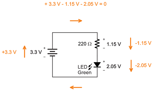
If you guessed from your measurements that adding up the voltages across each part in the circuit has to add up to the supply voltage, you guessed correctly.
Think about the micro:bit module’s 3.3 V supply as a (positive) increase in voltage and the parts in the LED circuit as a (negative) decrease in voltage.
Add those positive and negative voltages, and the result should be zero, in theory. In practice, your measurements should add up to something close to zero.
Did You Know?
This is an application of Kirchhoff's voltage law (abbreviated KVL), which states: “The directed sum of the potential differences (voltages) around any closed loop is zero.” When parts in a circuit are connected end-to-end like the resistor to the LED, they are connected in series.
Learn more: https://en.wikipedia.org/wiki/Kirchhoff%27s_circuit_laws.
Try This
You can change the resistor, and the sum of voltages measured across the LED and resistor should still add up to the supply voltage.
- Replace the 220 Ω resistor with the 1000 Ω one. The color code for the 1000 Ω resistor is brown-black-red.
- Measure the voltages again.
Did they still add up to 3.3 V?
Your Turn
Red LEDs use slightly less voltage.
- Try replacing the green LED with a red LED, and then measure the voltage again.
Did you notice a difference in the voltages? Did they still add up to 3.3 V?