Schematics and Building the Circuits
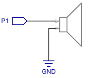
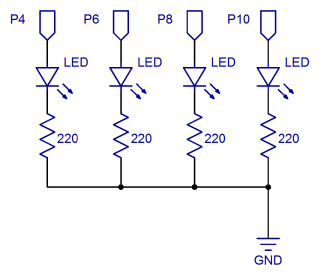
Figure 1 shows the schematics for connecting the 4-Directional Tilt Sensor, piezo speaker and 4 LED lights.
Figure 1 – Tilt Tones Schematics (BASIC Stamp HomeWork Board)
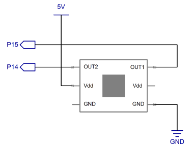
220 ohm resistors are built into the HomeWork Board.
If you are using a HomeWork board, you do not need to add the 220 ohm resistors shown in the schematic above to your breadboard, as shown in Figure 2. The little tiny chips next to the I/O pin socket labels are surface-mount 220-ohm resistors. However, if you are using the BASIC Stamp Board of Education, you will need to use a 220 ohm resistor on the breadboard for each LED.
Figure 2 – Tilt Tones Wiring Diagram (BASIC Stamp HomeWork Board)
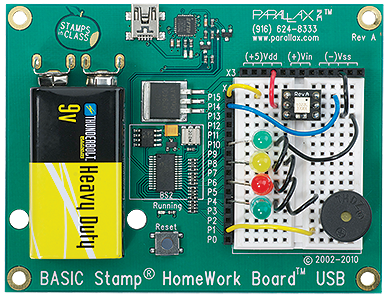
When you have finished setting up your board, it should look something like the wiring diagram in Figure 2. If your LED leads are too long, they can be cut, but be sure to make note of which side is the cathode and which is the anode. If you look at the top of the LED, the cathode is the side where the edge is either flattened or has a small notch in it.