Schematics and Building the Circuits
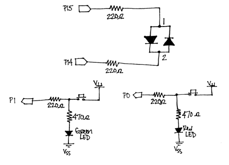
Figure 1 shows the schematic for the game board. Build the circuit shown below, paying close attention to the polarity of your LEDs. Before continuing, check that your circuit meets the following criteria:
- The shorter ends (cathodes) of the red and green LEDs are connected to ground
- The shorter end (cathode) of the bi-color LED is connected to pin 14
Figure 1 - Game Board Schematic
Using Electrical Connections to Control LEDs
The red and green LEDs are added to the circuit so the player can keep track of which button corresponds to what color. They also light up when a button is pressed so the player can imitate the pattern shown by the bi-color LED. Instead of writing additional code to monitor the pushbutton state and then turn the LED on or off depending on that state, we can connect the LED so that it only emits light when the connection has been closed between the pushbutton terminals. For more information, see What’s a Microcontroller? Chapter 3, Activity #1.
You might want to trim the LED leads so they can be mounted closer to the pushbuttons. If you decide to do this for your application and accidentally cut the leads so you’re not sure which one is shortest anymore, all is not lost, and the cathode can still be determined. If you look at the top of the LED, you will notice that one edge is either flattened or has a small notch in it. Whichever side has this marking is the cathode.
Testing 1, 2, 3…
Before continuing, it’s always a good idea to check your wiring for any errors. The easiest way is to run a program that tests each aspect of your circuit.
- Run HardwareTest.bs2 and check that the following happens:
- The bi-color LED blinks first red, then green
- When no pushbutton has been pressed, the Debug Terminal reads:
“IN0 = 0” and “IN1 = 0” - When you push the bottom pushbutton:
- The red LED turns on
- The Debug Terminal displays: “IN0 = 1” and “IN1 = 0”
- When you push the top pushbutton:
- The green LED turns on
- The Debug Terminal displays: “IN0 = 0” and “IN1 = 1”
' HardwareTest.bs2
' Tests the functionality of each piece of your circuit.
' {$STAMP BS2}
' {$PBASIC 2.5}

displayRed   PIN   15
displayGreen PIN   14

DO
  HIGH displayRed       ' Red
  LOW displayGreen
  PAUSE 200

  HIGH displayGreen     ' Green
  LOW displayRed
  PAUSE 200

  DEBUG HOME, ? IN0     ' Display PB States
  DEBUG ? IN1

  PAUSE 100
LOOP
Troubleshooting
If your code worked as directed, you’re free move on to the next section! However, if your circuit did not work as described above, here are some quick troubleshooting tips:
- If the bi-color LED blinks green, then red:
- Double check and make sure the cathode and anode are connected properly. Flip the LED around and see if that fixes the problem.
- If the red and green LEDs do not emit light when the buttons are pressed:
- Double check and make sure the cathode and anode are connected properly. Flip the LED around and see if that fixes the problem.
- Check the wiring on the board. The LED should not be directly connected to any pushbutton terminal, and should be as follows:
- The LED’s anode should be connected in between the two pushbutton terminals.
- The 470 Ω resistor should be connected to the bottom right pin of the pushbutton and to the anode of the LED.
- The LED’s cathode should be connected just above the top pushbutton terminal.
- If both LEDs emit light when a button is pressed:
- Check that none of the resistor leads are touching. You may choose to trim the resistor leads as well to prevent this from happening.
Random vs. Pseudo-Random Numbers
One of the most important parts of the game is the bi-color LED emitting random light patterns. This can be accomplished using the BASIC Stamp’s RANDOM command. This command generates a series of pseudo-random numbers ranging from 0 to 65535. By looking at a single bit of the pseudo-random number generated, we can program the bi‑color LED to blink green or red depending on if the value of that bit is 0 or 1.
Unfortunately, things aren’t quite that simple. You may have noticed that the term “pseudo-random” is used. This is because the BASIC Stamp can only generate what’s known as pseudo-random numbers. This means that even though the number generated appears random, it is really generated based on a logical operation. This operation uses the initial value (also known as the “seed”) to tap into a sequence of 65535 seemingly random numbers. At the start of our program, this value will always be zero, which in turn will generate the same sequence of numbers—and the LED will blink the same red-green pattern. This wouldn’t be very challenging for our game, so we’ll have to apply other coding techniques to generate a more desirable set of random numbers.
In RandomTest.bs2, we will accomplish this by using the BUTTON command. This command monitors the state of a button, and does not allow the code to move on until the state changes. Since the user can’t accurately time when they push a button, the variable generateColor will keep tapping into the sequence of pseudo-random numbers until the player presses the bottom pushbutton.
Run RandomTest.bs2 and:
- Make sure the bi-color LED emits random light patterns
- Press the reset button a few times to verify the pattern is different each time
' RandomTest.bs2
' Tests that the bi-color LED blinks random red-green patterns.

' {$STAMP BS2}
' {$PBASIC 2.5}

displayRed      PIN   15                          ' Red Pin
displayGreen    PIN   14                          ' Green Pin

btnWrk          VAR   BYTE                        ' Var for BUTTON command
generateColor   VAR   WORD                        ' Random number variable
displayColor    VAR   generateColor.BIT0          ' Bit 0 of random number

Begin_Game:

  RANDOM generateColor                            ' Create a random number
  BUTTON 0, 1, 100, 250, btnWrk, 0, Begin_Game    ' Do not continue until
                                                  ' button is pressed
  DO
    IF (displayColor = 1) THEN                    ' If bit0 of the random
      HIGH displayRed                             ' number generated is 1,
      LOW displayGreen                            ' display the color red.
      PAUSE 500
    ELSEIF (displayColor = 0) THEN                ' If bit0 of the random
      HIGH displayGreen                           ' number generated is 0,
      LOW displayRed                              ' display the color green.
      PAUSE 500
    ENDIF

    LOW displayRed                                ' Turn LED off before next
    LOW displayGreen                     ' color
    PAUSE 500

    RANDOM generateColor                          ' Generate new random number
  LOOP                                            ' Loop forever