Schematics and Building the Circuits
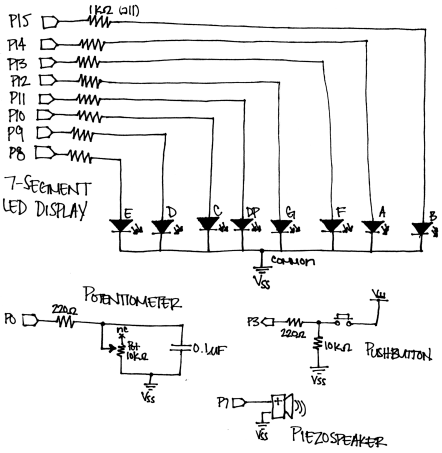
Not only does this activity provide another useful application for your WAM Kit, but it is also a great lesson on optimizing your breadboard real estate. There are a lot of components to fit onto the board, so we need to make the most of the space available. Figure 1 shows the schematic for this mini timer.
If you have difficulties assembling the timer, check this Parallax forum thread for more help.
Figure 1 - Mini Timer Schematic
Testing the Circuit
Once everything is wired, it’s important to check that everything is wired correctly. The program below will test each aspect of the circuit in one shot. Make sure you have the full source code for this project from the previous page, then run TestCircuit.bs2 and verify that the following occurs:
- The piezospeaker plays a tone
- The 7-Segment LED displays the numbers 0–9
- The decay time of the potentiometer ranges from about 1–600
- The pushbutton state is 1 when the button is pressed and 0 when the button is not pressed.
' TestCircuit.bs2
' Test each electrical component to be sure things were wired correctly.

' {$STAMP BS2}
' {$PBASIC 2.5}

time     VAR    Word                      ' Variable space for decay time

OUTH = %00000000                          ' Clear LED display
DIRH = %11111111                          ' Set pins 8-15 to outputs

FREQOUT 7, 100, 3500                      ' Test speaker
PAUSE 100
FREQOUT 7, 100, 3500

OUTH = %11100111                          ' 0
PAUSE 500
OUTH = %10000100                          ' 1
PAUSE 500
OUTH = %11010011                          ' 2
PAUSE 500
OUTH = %11010110                          ' 3
PAUSE 500
OUTH = %10110100                          ' 4
PAUSE 500
OUTH = %01110110                          ' 5
PAUSE 500
OUTH = %01110111                          ' 6
PAUSE 500
OUTH = %11000100                          ' 7
PAUSE 500
OUTH = %11110111                          ' 8
PAUSE 500
OUTH = %11110110                          ' 9

DO
  HIGH 0                                  ' Test potentiometer
  PAUSE 100
  RCTIME 0, 1, time
  DEBUG HOME, "time = ", DEC5 time, CR    ' Display decay time

  DEBUG ? IN3                             ' Display PB states
LOOP
While running this program, one important thing to check is the range of decay times for the potentiometer, which will be used to change the display of the 7-Segment LED from 0–9. Using this range, we can calculate the decay time interval for each minute, ensuring that the minutes complete a full cycle with the potentiometer. Each potentiometer can vary, so for the most accurate results it is very important that you check the range for your potentiometer.
For example, say your potentiometer range was 1–594. Since we want to display 10 total digits (0–9), we can divide 594 by 10 to get a decay time increment of 59.4. This means we’ll want the number displayed on the 7-Segment LED to change whenever the decay time increases by 59:
|
Minute |
0 |
1 |
2 |
3 |
4 |
5 |
6 |
7 |
8 |
9 |
|
Decay Time Value |
1 |
60 |
119 |
178 |
237 |
296 |
355 |
414 |
473 |
532 |
TestNumbers.bs2
This brings us to our next test program, TestNumbers.bs2. Run this program and verify that the 7-Segment LED displays the numbers 0–9 as the user rotates the potentiometer.
' TestNumbers.bs2
' Test that the numbers increase from 1-9 when turning the pot.

' {$STAMP BS2}
' {$PBASIC 2.5}

index    VAR    Nib
time     VAR    Word

OUTH = %00000000                ' Clear LED display
DIRH = %11111111                ' Set pins 8-15 to outputs

DO
  HIGH 0
  PAUSE 100
  RCTIME 0, 1, time

  LOOKDOWN time, <= [ 1, 60, 119, 178, 237, 296, 355, 414,
                     473, 532 ], index

  LOOKUP index, [ %11100111, %10000100, %11010011, %11010110,
                  %10110100, %01110110, %01110111, %11000100,
                  %11110111, %11110110 ], OUTH
LOOP
This program uses the LOOKUP and LOOKDOWN commands to display digits on the 7‑Segment LED. First, the program takes an RCTIME measurement and stores it in the variable time.
HIGH 0
PAUSE 100
RCTIME 0, 1, time
The LOOKDOWN table then uses the value stored in time to determine which number in the list time is smaller than or equal to. It then loads that number’s entry number (which is 0–9 in this case) into the variable index.
LOOKDOWN time, <= [ 1, 60, 119, 178, 237, 296, 355, 414,
                   473, 532 ], index
Lastly, the LOOKUP table uses the value in index to display the proper number on the 7‑Segment LED. The corresponding binary value is then loaded into the OUTH variable.
LOOKUP index, [ %11100111, %10000100, %11010011, %11010110,
                %10110100, %01110110, %01110111, %11000100,
                %11110111, %11110110 ], OUTH