Build the Circuit
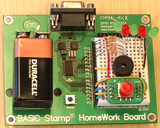
Figure 1 is the schematic and Figure 2 shows the parts placement for this circuit.
- Build your circuit as shown below.
Figure 1 - Christmas Caroler Schematic
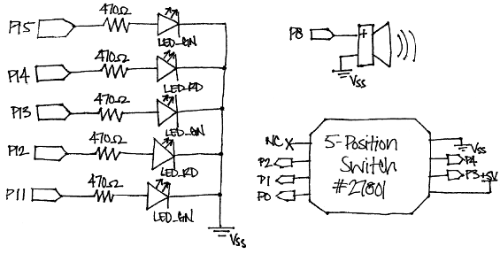
Figure 2 - Christmas Caroler Wiring Photo
Testing the Circuit
Once everything is wired, it’s good to be sure that everything is wired correctly. That way, you will always know that your circuit is functional, and won’t waste time trying to correct perfectly good code when the problem really lies in your wiring.
- Unzip the project code.
- Run TestCarolingDevice.bs2 and make sure that:
- All LEDs turn on
- The piezospeaker plays a tone
- All 5 positions (up, down, left, right, and pressed) display on the Debug Terminal
' TestCarolingDevice.bs2
' Tests that the Caroling Device is wired correctly.

' {$STAMP BS2}
' {$PBASIC 2.5}

HIGH 15                       ' Turn on all LEDs
HIGH 14
HIGH 13
HIGH 12
HIGH 11

FREQOUT 8, 2000, 3000         ' Play a tone

DEBUG CLS,                    ' Display directional graph
"            ", CR,
"     |      ", CR,
"   -   -    ", CR,
"     |      ", CR

' Display which direction is pressed on the 5-Position Switch
DO
  IF (IN0 = 0) THEN DEBUG CRSRXY, 2, 2, "<" ELSE DEBUG CRSRXY, 2, 2, " "
  IF (IN1 = 0) THEN DEBUG CRSRXY, 5, 4, "v" ELSE DEBUG CRSRXY, 5, 4, " "
  IF (IN2 = 0) THEN DEBUG CRSRXY, 8, 2, ">" ELSE DEBUG CRSRXY, 8, 2, " "
  IF (IN3 = 0) THEN DEBUG CRSRXY, 5, 2, "o" ELSE DEBUG CRSRXY, 5, 2, " "
  IF (IN4 = 0) THEN DEBUG CRSRXY, 5, 0, "^" ELSE DEBUG CRSRXY, 5, 0, " "
  PAUSE 20
LOOP