Schematics and Building the Circuits
Figure 1 below shows the schematic for the Magic BS2 board, and Figure 2 displays the optional mounting bracket assembly for the LCD display.
Figure 1 – Magic BS2 Board Schematic
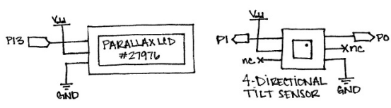
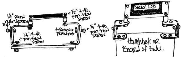
Figure 2 – Optional Mounting Bracket Assembly
Not sure how to wire circuits from schematics? No problem! Parallax offers another video tutorial on exactly that topic: How to Wire Circuits from Schematics.
Testing the Circuit
Once your circuit is wired, it’s a good idea to test that everything is working properly before developing code. The program below (also included in the source code download zip) displays a message on the Serial LCD and displays the states of the 4-Directional Tilt Sensor using the Debug Terminal.
Code:
' MagicBS2Board_Test.bs2
' Tests the functionality of the board

' {$STAMP BS2}
' {$PBASIC 2.5}

LCDpin    PIN    13                    ' Declare LCD pin

DEBUG CLS                              ' Clear the Debug Terminal

SEROUT LCDpin, 84, [22, 12]            ' Initialize the LCD
PAUSE 5

SEROUT LCDpin, 84, ["Testing..."]      ' Display test message

DO
  DEBUG BIN1 IN0, "  ", BIN1 IN1, CR   ' Display tilt states
  PAUSE 300                            ' at human speeds
LOOP
Another thing to check when running this code is to monitor how the 4-Directional Tilt Sensor responds when being shaken. We will need to determine what pattern emerges (if any) so that we can track when the board is moving and when it’s not, inside the code.
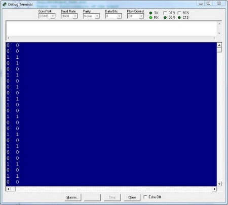
Figure 3 is a snippet of the tilt sensor’s states when being shaken. Notice that the state on at least one pin changes almost every time a reading is taken. But you should also notice that sometimes, the state remains the same. This will be key information as we put together our final program code!
Figure 3 – Debug Terminal Output of Tilt Sensor’s States