How the led_blink Script Controls the LED Circuit
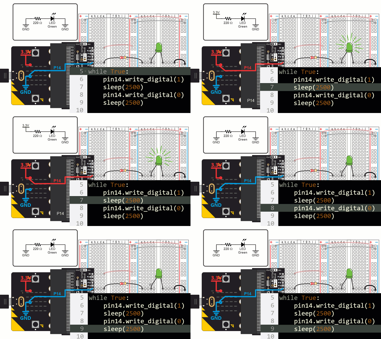
This animation shows how the led_blink script causes the micro:bit to alternate between connecting P14 to the 3.3 V (+) and GND (-) power connections.
(View full-size: blink-light-script-circuit-how.mp4)

The first statement in the led_blink script's while True loop is pin14. write_digital(1). This causes the micro:bit to connect P14 to its 3.3 V supply. Since the LED circuit on the breadboard is connected to P14, it turns the light on, just like when you connected it to a socket by the red (+) line in the bus strip. Then, sleep(2500) tells the micro:bit to wait for 2.5 s before continuing. The effect is that the light stays on during that time.
When the script reaches pin14.write_digital(0), it causes the micro:bit to connect P14 to its GND (0 V) supply. This is the same as if you were to connect the LED’s resistor to a socket by the blue (-) line on the bus strip. Since the other end of the LED circuit is also connected to GND, it means there’s no electrical pressure across the LED circuit, so no current flows through it and the LED does not emit light. After that, sleep(2500) leaves the light off for 2.5 s before the while True loop repeats.
Try This: Blink Timing
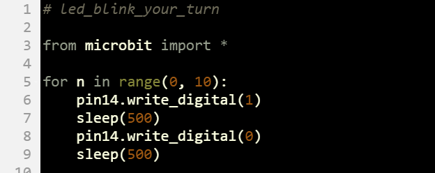
The for ...in range(...) loop isn’t just for counting. You can also use it to repeat statements a certain number of times without making use of the value of the counting variable. Here is an example where for n in range(0, 10): makes the light blink 10 times.
- Change the project name to led_blink_your_turn.
- Update your script to match the one below, then click Save.
- Click Send to micro:bit.
- Verify that the light blinks 10 times.

