Did You Know? Active vs. Resting, Pull-down vs. Pull-Up
When this pushbutton is pressed, it is in its active state. If you think of GND as a “low” voltage, and 3.3 V as a “high” voltage, a pushbutton that sends a 3.3 V high signal when you press it is considered active high. When a pushbutton is not pressed it is in a 0 V, low resting state.
The 10 kΩ resistor connected to GND in the circuit below is called a pull-down resistor. Because the 10 k resistor is connected to ground, it “pulls down” the pushbutton to a GND = 0 V resting state voltage when the button is not pressed. The circuit also applies that resting state voltage to P6. On the other hand, when the button is pressed, the circuit applies 3.3 V to P6.
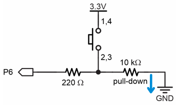
Without the pull-down resistor, a microcontroller’s I/O pin that’s set to input could “float” in response to nearby electric fields, such as the static electricity that builds up on people as they shuffle along the floor. That is why a floating input often switches from sensing 0 to 1 and back to 0 for no apparent reason. It’s also why a resistor that pulls the resting state voltage (either down to GND or up to 3.3 V) is so important.
When the button is pressed, it is in its active state. P6 becomes connected to 3.3 V through the 220 Ω resistor, and that is called active-high. A small amount of current also passes through the 10 kΩ resistor, but not through the 220 Ω one. That’s because as an input, an I/O pin is invisible to the circuit. It does not supply or draw any voltage or current. All it does is sense if voltage is above 2.3 V or below 1.0 V.
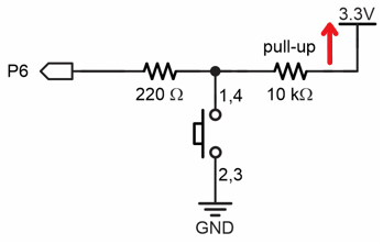
A pushbutton circuit can also be built with reversed 3.3 V and GND connections. In other words, the jumper wire could be connected to GND and the 10 kΩ resistor could be connected to 3.3 V. With the 10 kΩ resistor connected to 3.3 V, it is called a pull-up resistor because the resting state (not-pressed) voltage would be “pulled up” to 3.3 V. Its active state, while pressed would be 0 V, or active-low.
For prototyping, that 220 Ω resistor protects the microcontroller against a variety of circuit mistakes. (The 220 Ω resistor maybe could be replaced by a simple wire, but that’s typically for a final design.) The most common scenario is a script that makes a pin an output that sends 3.3 V through a wire to GND = 0 V. Without that 220 Ω resistor to “resist” the flow of current, some microcontrollers I/O pins can become damaged by trying to supply too much current.
DO NOT TRY THIS WITH YOUR MICRO:BIT!
Your Turn
There is currently a pushbutton on the breadboard with no voltage, I/O pin, or pull resistor connected. Create an active-low pushbutton with a pull-up resistor. Write a script to test the circuit. Hints:
- Use the pushbutton with pull-up schematic in the Did You Know section above.
- Connect the 220 Ω resistor between the pushbutton’s pin 1 and P9.
- Connect a 10 kΩ resistor between the pushbutton’s pin 4 and a 3V (+) bus strip socket.
- Connect a (preferably black) jumper wire between the pushbutton’s pin 3 and a GND (-) bus strip socket.
- Use the micro:bit Python Editor to open the pushbutton_test.hex test script you saved in Build and Test a Pushbutton.
- Modify it to test for P9 instead of P6. That means all instances of pin6 need to be changed to pin9 in the script.
- Click Send to micro:bit to flash the modified script into the micro:bit.
- Use the Serial monitor to verify that pin9.read_digital() returns 1 when the pushbutton is not pressed, and 0 when it is pressed.