As mentioned earlier, engineers sometimes use oscilloscopes to test signal activity in their product designs (inventions). Technicians sometimes use portable oscilloscopes to test signal activity in a device or machine they are maintaining or repairing. They typically compare their results to information in a repair manual that describes what to expect.
Other places where oscilloscopes are used are to test signals in inventions and robots. And, being able to use an oscilloscope to measure and diagnose signals can sometimes make the difference between a winning robot or contest entry, and one that’s not performing quite that well.
Oscilloscopes take practice to use, so whenever possible, these lessons will include examples of measuring signal activity (voltages that change over time) with an oscilloscope.
In this activity, you will:
- Measure the pushbutton and LED voltages with an oscilloscope
- Learn how the plotted data relates to what’s actually happening with the circuit voltages
- Study start pulses, which are used in electronics to initiate communication and other events
- Use oscilloscope trigger settings to align that start pulse with a certain time to make the plot easier to view.
Parts
Additional Parts for this Activity
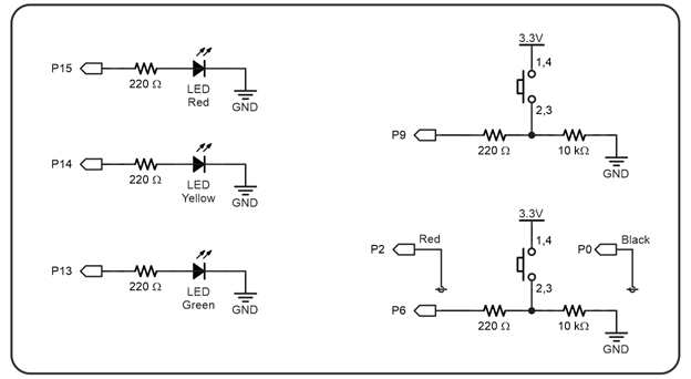
None—there are no new components; just the same pushbuttons and LEDS from the last activity Second Pushbutton.
Setup from Previous Activities
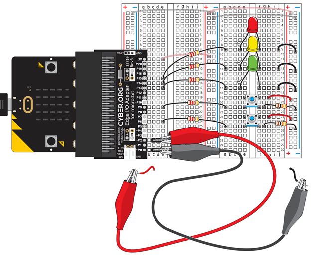
Circuit
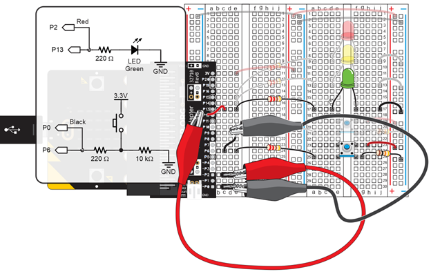
On a stand-alone oscilloscope, you would also have to connect a ground clip to GND. The multimeter module in the micro:bit script uses the micro:bit’s built-in ground connection as its reference ground. So, we can actually use both the black P0 and red P2 alligator clip leads as probes to measure voltages.
- Connect the black P0 alligator clip probe to P6.
- Connect the red P2 alligator clip probe to P13.