In this tutorial's activities, the pushbuttons you add will be used to control the lights from LED Lights. You will also use the alligator clip probes to test continuity between pushbutton terminals and voltages at key points in pushbutton circuits.
- If you already have the setup below built up from Measure Blinking Light with a Voltmeter (repeated below), then skip to the next page: Build & Test a Pushbutton.
- If you do not already have it built up:
- Use the schematic, wiring diagram, and Parts List from Earlier Activities below to get your setup to the starting point for this tutorial.
- Use the led_blink_list script to test and make sure each light turns on/off.
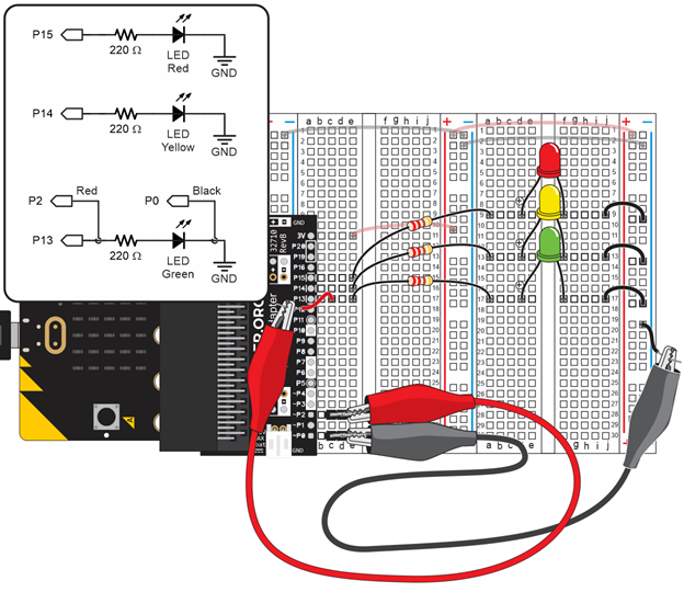
Parts Lists from Earlier Activities
Green, yellow and red LED circuits connected to P13, P14, and P15 from Blink Sequencing:
- (1) LED - Red
- (1) LED - Yellow
- (1) LED - Green
- (3) Resistors - 220 Ω (red-red-brown-gold)
- (3) Jumper wires - black
Alligator clip probes from First Electrical Connections with a Breadboard and recently used in Measure Blinking Light with a Voltmeter:
- (1) Alligator clip probe - red
- (1) Jumper wire - red
- (1) Alligator clip probe - red
- (1) Jumper wire - red
Always Keep These On Your Board
Jumper wires that connect the 3V to the (+) bus strips and GND to the (-) bus strips from Set Power for Circuits:
- (2) Jumper wires - red
- (2) Jumper wires - black
3-pin headers from First Electrical Connections with a Breadboard that connect the alligator clip probes to P2 and P0:
- (2) 3-pin headers
If you completed Measure Resistance, leave these Ohmmeter Circuit parts connected to your board too:
- (2) 3-pin headers
- (1) Resistor - 2 kΩ (red-black-red-gold)
- (1) Jumper wire - yellow