

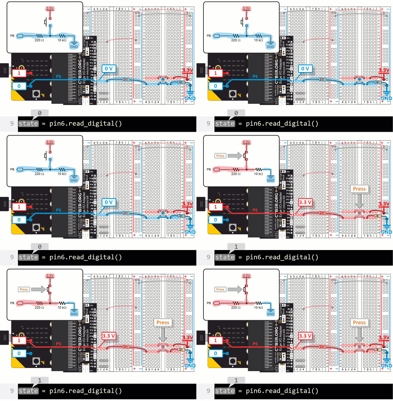
Pushbuttons are common in devices we use every day. How many pushbuttons do you see on the keyboard you are using? What other devices do you use with pushbuttons? Does your game controller have more than just two buttons? How about your phone, maybe power, volume up and volume down?

Just as many devices have pushbuttons, some inventions and prototypes need more than just the two (A & B) pushbuttons built into the micro:bit. So, you might find experience with building testing and incorporating pushbuttons into projects useful at some point. Understanding how they work can also come in handy, especially if a prototype with pushbuttons isn’t behaving as expected.
In these activities, you will:
These lessons use a specific kit and build on earlier material.
You will need:
Complete these tutorials first:
You will be able to:
Although this activity just uses pushbuttons to control lights, you will use them to control other devices, including a motor, in upcoming activities.
In this tutorial's activities, the pushbuttons you add will be used to control the lights from LED Lights [7]. You will also use the alligator clip probes to test continuity between pushbutton terminals and voltages at key points in pushbutton circuits.
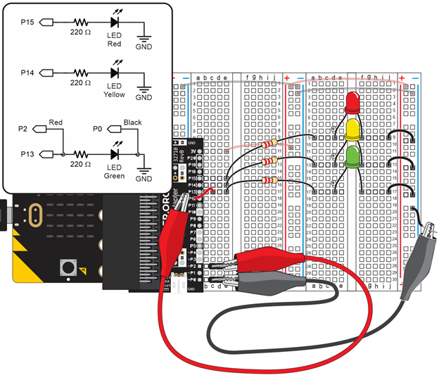
Green, yellow and red LED circuits connected to P13, P14, and P15 from Blink Sequencing [10]:
Alligator clip probes from First Electrical Connections with a Breadboard [11] and recently used in Measure Blinking Light with a Voltmeter [8]:
Jumper wires that connect the 3V to the (+) bus strips and GND to the (-) bus strips from Set Power for Circuits [12]:
3-pin headers from First Electrical Connections with a Breadboard [11] that connect the alligator clip probes to P2 and P0:
If you completed Measure Resistance [13], leave these Ohmmeter Circuit parts connected to your board too:
As mentioned earlier, sometimes the two pushbuttons on the micro:bit just aren't enough! If this ever happens with your inventions and prototypes, it helps to be able to add more to a breadboard.
In this activity, you will:
These are the parts you will add to the setup you started with in Setup from Previous Activities.
(1) Resistor - 220 Ω (red-red-brown-gold)
(1) Resistor - 10 kΩ (brown-black-orange-gold)
(1) Jumper wires - red
(1) Pushbutton - New part, see Pushbutton diagram

A part drawing with numbers by each pin is called a pin map. Pin maps are normally published in part datasheets. Engineers and technicians use schematics and pin maps when designing, troubleshooting, and maintaining circuits. The schematic shows how the parts are interconnected, and the pin map shows how the pin numbers in the schematic relate to the physical part. This pushbutton can be rotated 180°, and the pin map still applies. That’s not common! Most parts have a reference mark by pin 1 and cannot be rotated, for example the two black chips, an 8-pin op amp and a 3-pin transistor from your kit.


The pushbutton_test script displays whether or not the pushbutton is pressed as values of 1 and 0. These values are often called states. With this pushbutton circuit and script, a state of 1 indicates pressed, and 0 indicates not pressed.
# pushbutton_test

from microbit import *

state = 0
display.off()
pin6.set_pull(pin6.NO_PULL)

while True:
    state = pin6.read_digital()
    print("state = ", state)
    sleep(250)


(Answers are in the Teacher's Guide.))
This script is short, but it contains some important instructions that are unique to the micro:bit module hardware.
To begin, the state = 0 statement just creates a variable named state that will be used inside the while True loop.
state = 0
The micro:bit module’s P6 pin is part of the module's 5x5 LED display grid. The display.off() call prevents the LED circuits built into the micro:bit from interfering with the pushbutton circuit you just built on the breadboard.
display.off()
The 10 kΩ resistor connected to the pushbutton is called a pull-down resistor. More about that later! P6 also has an internal pull-down resistor enabled by default, and this statement disables it since a 10 kΩ pulldown resistor has been added to the circuit on your breadboard. Many microcontrollers used in
pin6.set_pull(pin6.NO_PULL)
Inside the main loop, when the pushbutton is pressed, the circuit applies 3.3 V to the P6 pin. The pin6.read_digital() call returns 1 when it detects 3.3 V. If the button is released, the circuit applies 0 V to the pin, and pin6.read_digital() returns 0 instead. In state = pin6.read_digital(), the state variable stores that 1 or 0 result.
while True:
    state = pin6.read_digital()
Next, the print statement displays "state = " followed by the 1 or 0 that just was stored in the state variable.
print("state = ", state)
Last in the loop, the sleep(250) call just slows down the display to make it easier to observe the transitions from 0 to 1 and 1 to 0.
sleep(250)
The binary (1 or 0) value returned by the pin6.read_digital() method can be used as the argument to turn the LED light on and off in pin13.write_digital(state). When state is 1 because the button is pressed, pin13.write_digital(state) becomes pin13.write_digital(1). This sets the P13 LED light to on. When the state variable is 0 because the button is not pressed, pin13.write_digital(state) becomes pin13.write_digital(0). This sets the LED light to off.
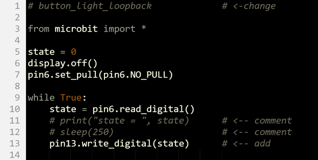
A light that a microcontroller turns on and off can be considered a binary (2-state) output circuit. Likewise, a pushbutton circuit can be considered a binary input circuit. The microcontroller monitors the pushbutton circuit to find out which of two states the button is in: pressed or not pressed. The microcontroller does this by monitoring the voltage that changes at a certain point in the circuit in response to the pushbutton being pressed.
A pin.read_digital() call sets a micro:bit I/O pin to input. As an input, an I/O pin monitors the voltage of a circuit that’s connected to it without affecting the circuit. The circuit behaves the same regardless of whether the I/O pin is connected or not.
Inside the micro:bit’s microcontroller, there is memory—like a variable—called an input register that stores the voltages measured by I/O pins as 1s and 0s. Each memory element that stores a 1 or 0 is called a bit. Likewise, a register bit refers to each memory element that stores a 1 or 0 to indicate the voltage applied to an I/O pin set to input.
When an I/O pin input register bit stores a 1, it means the pin detected a voltage that was above 2.3 V. If it instead stores a 0, it means the voltage was below 1 V. If the voltage is in the 1 to 2.3V range, the register just keeps the most recent measurement that was above 2.3 V or below 1 V. The pin6.digital_read() method returns that binary value (1 or 0) that the P6 input register bit stores.
The binary (1 or 0) value returend by the pin6.read_digital() method returns can be used in decision making with if statements. When state is 1 because the button is pressed, code in this example script’s if statement will make the light turn on for 0.25 seconds. After that, the light is turned off for another 0.25 seconds. When state is 0, the statements that turn the light on are skipped, and the while True loop just repeatedly turns the P13 light off. The end result is that the light blinks while the button is pressed and held, and stays off when it is not pressed.
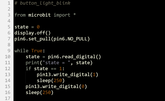
Write a script to make the light blink when the button is pressed but without using an if...statement. Hint: the 1/0 value from the pushbutton state can be used to turn the light on or off, and then sleep. After that, the script just needs to make sure it turns the light off and sleeps again before repeating the while True() loop.
Solution: The trick is to use the 1/0 value of state.
from microbit import *

state = 0
display.off()

while True:
    state = pin6.read_digital()
    pin13.write_digital(state)
    sleep(100)
    pin13.write_digital(0)
    sleep(100)
Let’s take a look inside the pushbutton to better understand how and why it changes the circuit when you press it. In this activity, you will:
In this activity, you will connect new parts, as well as make use of parts from a previous activity.
(1) Resistor - 220 Ω (red-red-brown-gold)
(1) Resistor - 10 kΩ (brown-black-orange-gold)
(1) Jumper wire - black
(1) Pushbutton
You will be using the alligator clip leads again in this activity. The 3 LED circuits are not used in this activity, but will be used again in the next one.

Remember from the Parts list in the Build & Test a Pushbutton activity’s Parts section that it has a pin map with pins 1, 2, 3, and 4? Since you will be probing various pairs of those pins with the micro:bit continuity tester, here it is again for reference.


This script will use the CYBERscope to probe the electrical connections when the button is pressed and not pressed.
Here is the pushbutton’s theory of operation. That’s the electronics-speak way of saying “how it works.”
Here are continuity tests you can perform to verify the pushbutton’s theory of operation. First, verify that the 1,4 pair is not connected to the 2,3 pair unless the pushbutton is pressed (and held to get your measurement).
Next, verify that the 1,4 and 2,3 pairs of pins are interconnected regardless of whether the pushbutton is pressed or not:
Looking inside the pushbutton, the legs that stick out of both sides of the pushbutton’s body are actually wires that pass all the way through. One of the wires forms legs 1 and 4, and the other forms legs 2 and 3. The button has a metal bar attached underneath and a springy material that keeps it floating above the two wires. When you press the button, the metal bar comes to rest atop the two wires.
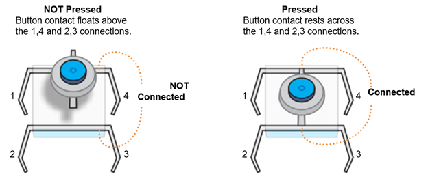
Since legs 1 and 4 are actually part of a single wire, they are always electrically connected, so a micro:bit continuity test will always display the checkmark. The same applies to legs 2 and 3.
When the button is not pressed, current cannot conduct between the 1,4 and 2,3 legs, so its connection is called open or an open circuit. When the button is pressed, current can conduct between the 1,4 and 2,3 legs, and the connection is called closed. Since this pushbutton is open when it is not pressed, it is called a normally open pushbutton. Though your kit does not have them, normally closed pushbuttons also exist, where their connection is closed when it is not pressed, and open when it is pressed.
When the button is not pressed, legs 1 and 4 are insulated from 2 and 3. So probing any of these pairs of pins will result in the micro:bit continuity tester’s LED display showing the not connected X: (4, 3), (4, 2), (1, 2), (1, 3). When you press and hold the pushbutton, the micro:bit continuity tester displays the connected checkmark instead.
In addition to checking pushbutton functionality with continuity tests, sometimes the voltage it applies to the micro:bit needs to be checked. In prototype tests and machine repairs, this is one of the first tests when pressing a button does not produce the desired result.
measure_P6_volts_with_cyberscope.hex [22]
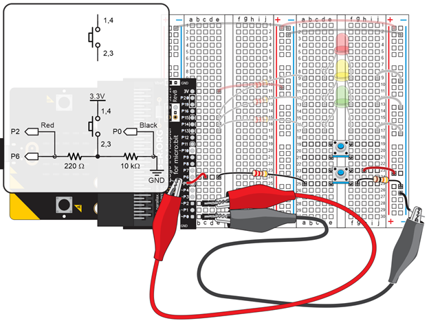

Release the pushbutton and verify that the measurement returns to a value close to 0 V.

When this pushbutton is pressed, it is in its active state. If you think of GND as a “low” voltage, and 3.3 V as a “high” voltage, a pushbutton that sends a 3.3 V high signal when you press it is considered active high. When a pushbutton is not pressed it is in a 0 V, low resting state.
The 10 kΩ resistor connected to GND in the circuit below is called a pull-down resistor. Because the 10 k resistor is connected to ground, it “pulls down” the pushbutton to a GND = 0 V resting state voltage when the button is not pressed. The circuit also applies that resting state voltage to P6. On the other hand, when the button is pressed, the circuit applies 3.3 V to P6.
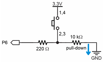
Without the pull-down resistor, a microcontroller’s I/O pin that’s set to input could “float” in response to nearby electric fields, such as the static electricity that builds up on people as they shuffle along the floor. That is why a floating input often switches from sensing 0 to 1 and back to 0 for no apparent reason. It’s also why a resistor that pulls the resting state voltage (either down to GND or up to 3.3 V) is so important.
When the button is pressed, it is in its active state. P6 becomes connected to 3.3 V through the 220 Ω resistor, and that is called active-high. A small amount of current also passes through the 10 kΩ resistor, but not through the 220 Ω one. That’s because as an input, an I/O pin is invisible to the circuit. It does not supply or draw any voltage or current. All it does is sense if voltage is above 2.3 V or below 1.0 V.
A pushbutton circuit can also be built with reversed 3.3 V and GND connections. In other words, the jumper wire could be connected to GND and the 10 kΩ resistor could be connected to 3.3 V. With the 10 kΩ resistor connected to 3.3 V, it is called a pull-up resistor because the resting state (not-pressed) voltage would be “pulled up” to 3.3 V. Its active state, while pressed would be 0 V, or active-low.
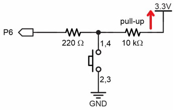
For prototyping, that 220 Ω resistor protects the microcontroller against a variety of circuit mistakes. (The 220 Ω resistor maybe could be replaced by a simple wire, but that’s typically for a final design.) The most common scenario is a script that makes a pin an output that sends 3.3 V through a wire to GND = 0 V. Without that 220 Ω resistor to “resist” the flow of current, some microcontrollers I/O pins can become damaged by trying to supply too much current.
DO NOT TRY THIS WITH YOUR MICRO:BIT!
There is currently a pushbutton on the breadboard with no voltage, I/O pin, or pull resistor connected. Create an active-low pushbutton with a pull-up resistor. Write a script to test the circuit. Hints:
Imagine that you want a light to blink red when nothing is sensed but to stop when an object is present, much like an automatic door opens when you step on a mat, but is closed the rest of the time. Write a script so that your new pushbutton pull-up circuit flashes the red LED without a pushbutton press and turns off when you press the pushbutton.
Solution:
Hint: Combine scripts from this activity and Build and Test a Pushbutton.
# pushbutton_pullup_with_red_LED

from microbit import *

state = 0
display.off()
pin9.set_pull(pin9.NO_PULL)

while True:
    state = pin9.read_digital()
    print("state = ", state)
    sleep(250)

    if state == 1:
        pin15.write_digital(1)
        sleep(250)
    pin15.write_digital(0)
    sleep(250)
In this activity, you will:
If you completed all of Inside the Pushbutton, all you will have to do here is replace a black jumper wire with a red one.
(1) Jumper wire - red


If you completed the Inside the Pushbutton > Your Turn [26] section, the circuit you built will have to be modified for this activity. For those of you who partially completed or skipped that activity, you will either be adding three or four of the parts shown below.

The pushbutton_test_x2 script displays the states of both pushbuttons in the Serial Monitor.
# pushbutton_test_x2

from microbit import *

state9 = 0
state6 = 0
display.off()
pin9.set_pull(pin9.NO_PULL)
pin6.set_pull(pin6.NO_PULL)

while True:
    state9 = pin9.read_digital()
    state6 = pin6.read_digital()
    print("state9:", state9, " state6:", state6)
    sleep(250)

The pushbutton_test_x2 script started as pushbutton_test, and was adapted for two pushbuttons through the following changes:
The button_light_blink_x2 script is the two-button, two-light version of the button_light_blink script from the Build and Test a Pushbutton activity’s Your Turn section [27].
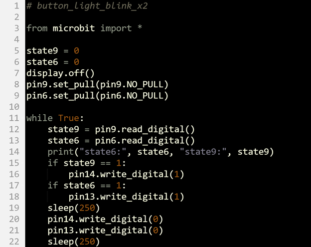
A pair of pushbuttons can be used to control whether a variable counts up or down. Take a look at the while True loop below:
while True:
    state9 = pin9.read_digital()
    state6 = pin6.read_digital()

    if state9 is 1:
        index = index + 1
        if index > 2:
            index = 0
    if state6 is 1:
        index = index - 1
        if index < 0:
            index = 2
Each if statement also has a nested if statement that restarts the count when it reaches a certain point. When up-counting, when the index variable reaches 3, it gets changed back to 0. When down-counting, when index reaches -1, it gets changed back to 2.
If you guessed that counting up or down might work with lists of pins and times, you are right! In the next Your Turn section, that index value will be used to access the 0, 1, and 2 elements in these pin and time lists (below). When counting up, the index variable will be used to fetch pin13, pin14, and pin15, then repeat again starting with pin13. When counting down, the index variable will be used to fetch pin15, pin14, pin13, pin15, pin14, pin13, and so on.
pin = [pin13, pin14, pin15]
time = [200, 200, 200]
With this application, you can hold the P9 pushbutton to make the lights turn on and off in a repeating green-yellow-red pattern. If you instead hold down the P6 pushbutton, the lights turn on and off in a repeating red-yellow-green pattern.

1. Solution.
# rotate_leds_leds_off

from microbit import *

pin = [pin13, pin14, pin15]
time = [200, 200, 200]
index = 0
state9 = 0
state6 = 0

display.off()
pin9.set_pull(pin9.NO_PULL)
pin6.set_pull(pin6.NO_PULL)

while True:
    state9 = pin9.read_digital()
    state6 = pin6.read_digital()

    if state9 is 1:
        index = index + 1
        if index > 2:
            index = 0
        pin[index].write_digital(1)
        sleep(time[index])
        pin[index].write_digital(0)

    if state6 is 1:
        index = index - 1
        if index < 0:
            index = 2
        pin[index].write_digital(1)
        sleep(time[index])
        pin[index].write_digital(0)
2. Solution.
#project_solution

from microbit import *

pin = [pin13, pin14, pin15]
time = [1500, 1000, 500]
index = 0
state9 = 0
state6 = 0

display.off()
pin9.set_pull(pin9.NO_PULL)
pin6.set_pull(pin6.NO_PULL)

while True:
    state9 = pin9.read_digital()
    state6 = pin6.read_digital()

    if state9 is 1:
        index = index + 1
        if index > 2:
            index = 0
        pin[index].write_digital(1)
        sleep(time[index])
        pin[index].write_digital(0)
        sleep(time[index])

    if state6 is 1:
        index = index - 1
        if index < 0:
            index = 2

        pin[index].write_digital(1)
        sleep(time[index])
        pin[index].write_digital(0)
        sleep(time[index])
3: Solution.
# buttons_with_leds_and_zip

from microbit import *

pin_list = [pin13, pin14, pin15]
time_list = [500, 1000, 1500]
state9 = 0

display.off()
pin9.set_pull(pin9.NO_PULL)

while True:
    state9 = pin9.read_digital()

    for pin, time in zip(pin_list, time_list):

        if state9 is 1:
            pin.write_digital(1)
            sleep(time)
            pin.write_digital(0)
            sleep(time)
As mentioned earlier, engineers sometimes use oscilloscopes to test signal activity in their product designs (inventions). Technicians sometimes use portable oscilloscopes to test signal activity in a device or machine they are maintaining or repairing. They typically compare their results to information in a repair manual that describes what to expect.
Other places where oscilloscopes are used are to test signals in inventions and robots. And, being able to use an oscilloscope to measure and diagnose signals can sometimes make the difference between a winning robot or contest entry, and one that’s not performing quite that well.
Oscilloscopes take practice to use, so whenever possible, these lessons will include examples of measuring signal activity (voltages that change over time) with an oscilloscope.
In this activity, you will:
None—there are no new components; just the same pushbuttons and LEDS from the last activity Second Pushbutton [30].
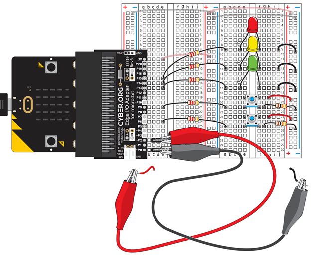
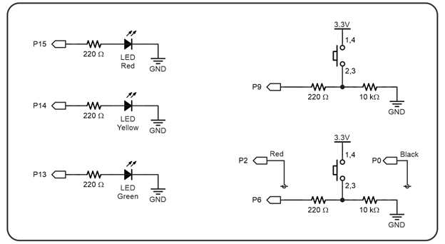
On a stand-alone oscilloscope, you would also have to connect a ground clip to GND. The multimeter module in the micro:bit script uses the micro:bit’s built-in ground connection as its reference ground. So, we can actually use both the black P0 and red P2 alligator clip leads as probes to measure voltages.
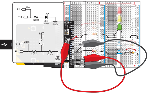
button_led_blink_with_plot.hex [31]
NOTE: Before the first pushbutton press, you might notice the red Ch2 voltage trace is plotting irregularly in the 0.5 to 1.5 V range. That’s because the LED pin is a floating input that has not been set to low or high by pin13.write_digital(0) or pin13.write_digital(1).
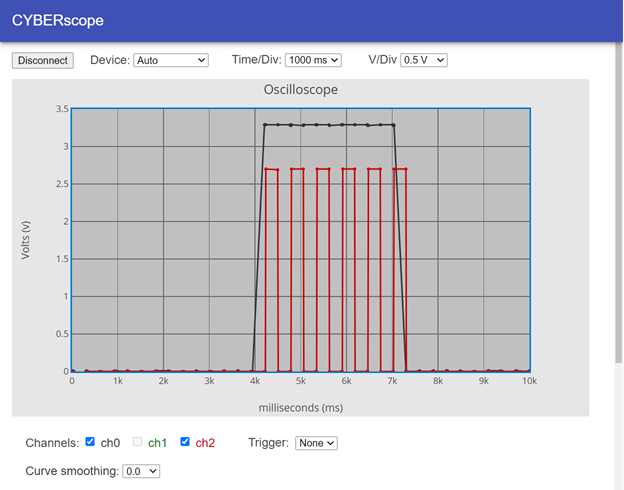
Also verify the following:
An oscilloscope is typically a separate piece of equipment. If we were using one, it wouldn’t be necessary to change the code because the oscilloscope has its own processor for monitoring and displaying measurements.
This script started as button_light_blink from the Build and Test a Pushbutton activity’s Your Turn section [27]. Since the micro:bit is functioning as its own oscilloscope, calls to plot(volts(pin0), "y0", volts(pin2), "y2") are added before and after statements that check the pushbutton and change the LED light on/off states.
In electronics, a “start pulse” from one device can cause on/off signals from another device. Those signals might contain information, like binary communication data, or they might be something like the return waves from an ultrasonic ranging pulse (that measures distance). To emulate these events, when the script you will use in this activity detects a button press, it will blink the light six times.
button_led_blink_6x_with_plot.hex [32]
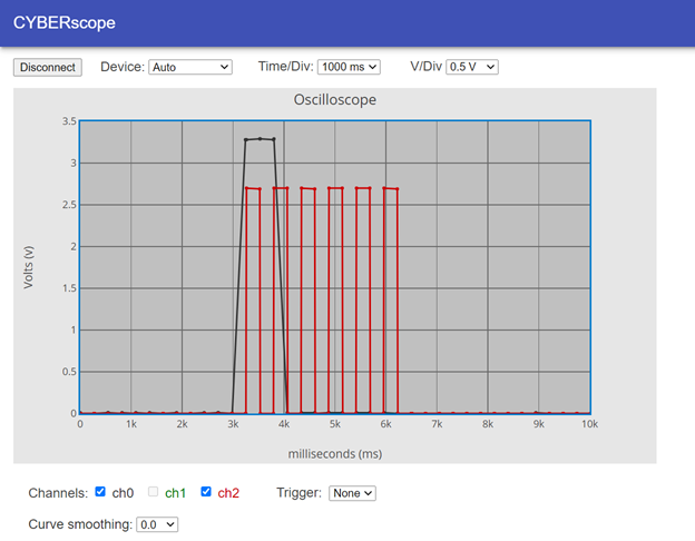
Sometimes, you have no way of knowing when an event like the button press will happen. If it happens when the plot is close to the right edge of the screen. After the signals leave the right side of the screen, they’ll actually wrap around to the left.
The CYBERscope trigger feature you experimented with in the Measure Lights with an Oscilloscope activity’s Your Turn section [33] is designed for situations like these because it can keep the plot activity that needs to be analyzed in the right position in the plot area.
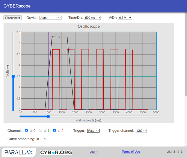
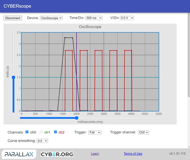
The CYBERscope trigger has rising and falling edge settings. A trigger edge is simply any part of the plot that passes the voltage trigger level. On the CYBERscope, the default trigger voltage is 1.5 V. It can be adjusted with a slider to the left of the plot, and is indicated by a turquoise horizontal line.
With its trigger set to Rise, an oscilloscope waits for two things:
After the oscilloscope has all that data, it positions the plot so that the voltage edge lines up with the trigger time. The CYBERscope’s default trigger time is 1/5th of the way into the plot. For example, if the total time axis is 5000 ms, the trigger time would be at 1000 ms. The time trigger is indicated by a vertical purple line, and can be adjusted by a slider below the plot.
Links
[1] https://www.parallax.com/product/whats-a-microcontroller-with-python-and-microbit/
[2] https://learn.parallax.com/tutorials/robot/cyberbot/get-started-microbit-and-python
[3] https://learn.parallax.com/tutorials/robot/cyberbot/writing-microbit-programs
[4] https://learn.parallax.com/tutorials/robot/cyberbot/computer-microbit-talk
[5] https://learn.parallax.com/tutorials/language/python/breadboard-setup-and-testing-microbit
[6] https://learn.parallax.com/tutorials/language/python/electrical-measurements
[7] https://learn.parallax.com/tutorials/language/python/led-lights
[8] https://learn.parallax.com/tutorials/language/python/led-lights/measure-blinking-light-voltmeter
[9] https://learn.parallax.com/tutorials/language/python/led-lights/blink-sequencing/script-and-tests
[10] https://learn.parallax.com/tutorials/language/python/led-lights/blink-sequencing
[11] https://learn.parallax.com/tutorials/language/python/breadboard-setup-and-testing-microbit/first-electrical-connections-5
[12] https://learn.parallax.com/tutorials/language/python/breadboard-setup-and-testing-microbit/set-power-circuits
[13] https://learn.parallax.com/tutorials/language/python/electrical-measurements/measure-resistance
[14] https://microbit.python.org
[15] https://learn.parallax.com/tutorials/robot/cyberbot/get-started-microbit-and-python/save-edit-scripts
[16] https://learn.parallax.com/tutorials/robot/cyberbot/get-started-microbit-and-python/flash-scripts-python-editor
[17] https://learn.parallax.com/tutorials/robot/cyberbot/get-started-microbit-and-python/use-serial-monitor
[18] https://learn.parallax.com/sites/default/files/content/Python/button/pb-top-button-digital-read.mp4
[19] https://python.microbit.org/
[20] https://learn.parallax.com/sites/default/files/content/Python/breadboard/hex/continuity_tester.hex
[21] https://cyberscope.parallax.com/
[22] https://learn.parallax.com/sites/default/files/content/Python/button/measure_P6_volts_with_cyberscope.hex
[23] https://python.microbit.org/v/2
[24] https://cyberscope.parallax.com
[25] https://learn.parallax.com/tutorials/language/python/sense-pushbutton-presses/build-and-test-pushbutton/script-and-tests
[26] https://learn.parallax.com/tutorials/language/python/sense-pushbutton-presses/inside-pushbutton/active-vs-resting-states
[27] https://learn.parallax.com/tutorials/language/spin/sense-pushbutton-presses/build-and-test-pushbutton/input-register-and
[28] https://learn.parallax.com/tutorials/led-lights/intro-lists
[29] https://learn.parallax.com/tutorials/language/python/led-lights/intro-lists/how-it-works
[30] https://learn.parallax.com/tutorials/language/python/sense-pushbutton-presses/second-pushbutton
[31] https://learn.parallax.com/sites/default/files/content/Python/button/button_led_blink_with_plot.hex
[32] https://learn.parallax.com/sites/default/files/content/Python/button/button_led_blink_6x_with_plot.hex
[33] https://learn.parallax.com/tutorials/language/python/led-lights/measure-light-oscilloscope/setting-trigger